

Shift operation device of automatic transmission
a technology of automatic transmission and operation device, which is applied in mechanical equipment, transportation and packaging, and gear shifting, etc., can solve the problems of large-sized devices, energy loss, and long gearshift time, and achieve the effect of reducing the operation tim
- Summary
- Abstract
- Description
- Claims
- Application Information
AI Technical Summary
Benefits of technology
Problems solved by technology
Method used
Image

Examples
first embodiment
[0055]Next, a description will be given for a part of a shift operation device used in the above-described automatic transmission 1.
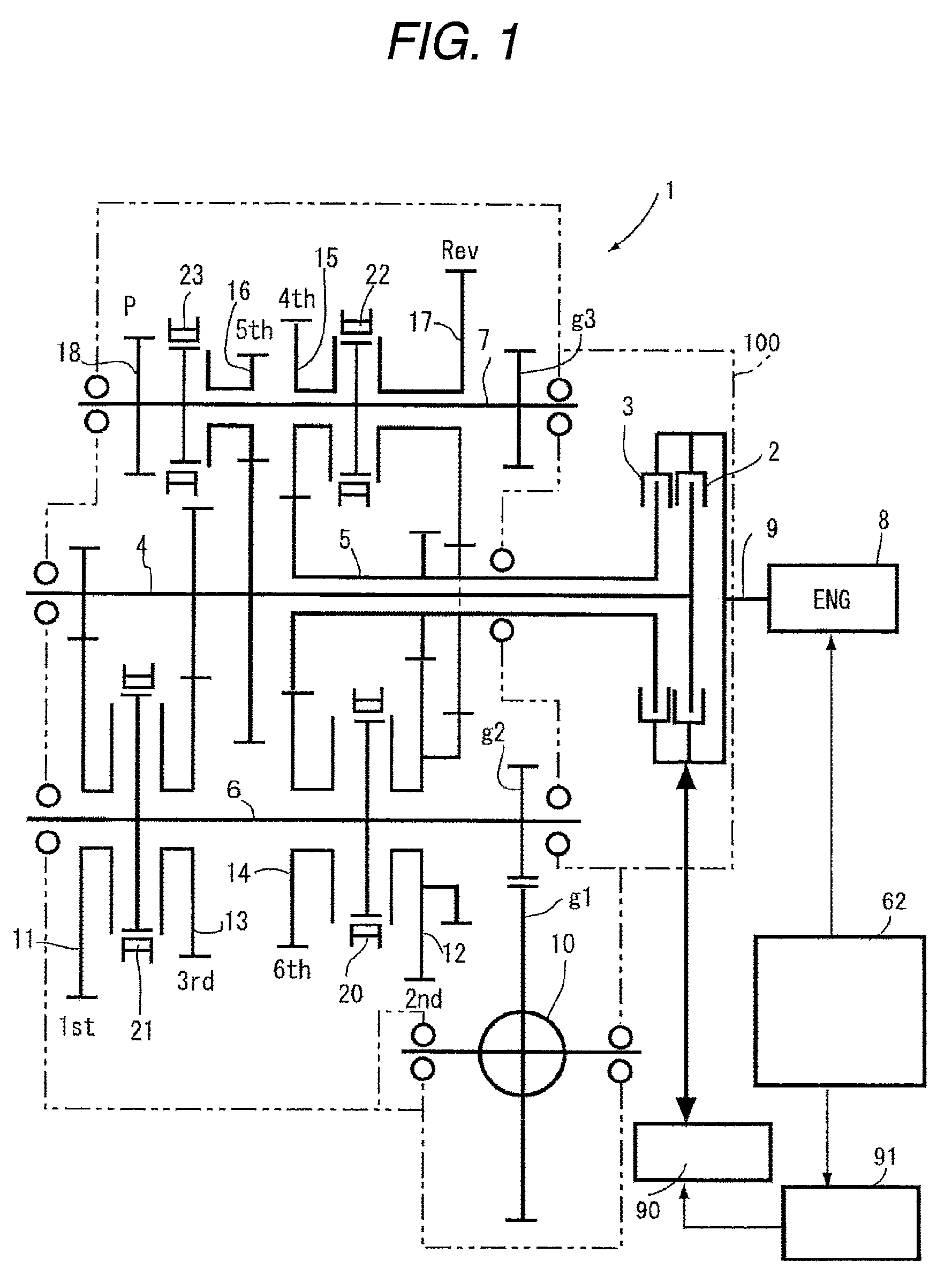
[0056]The shift operation device of the automatic transmission 1 is arranged inside a casing 100 (refer to FIG. 1) to transmit a slide-movement operation force to the shift forks 20 to 23. The shift operation device is shown in FIG. 2 and FIG. 3.
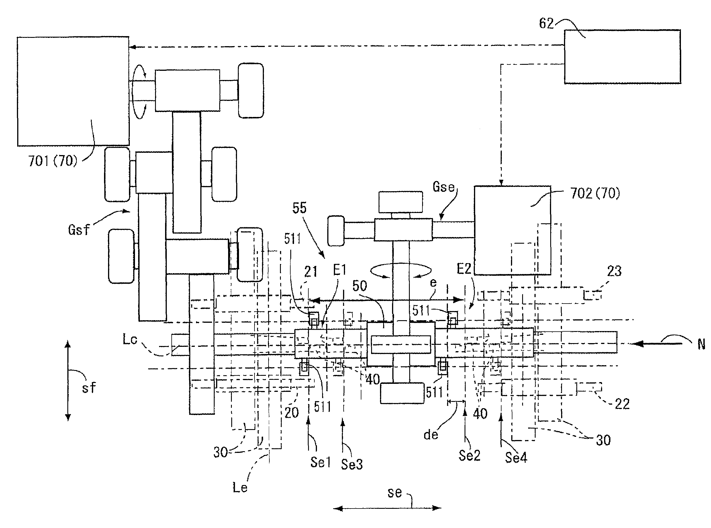
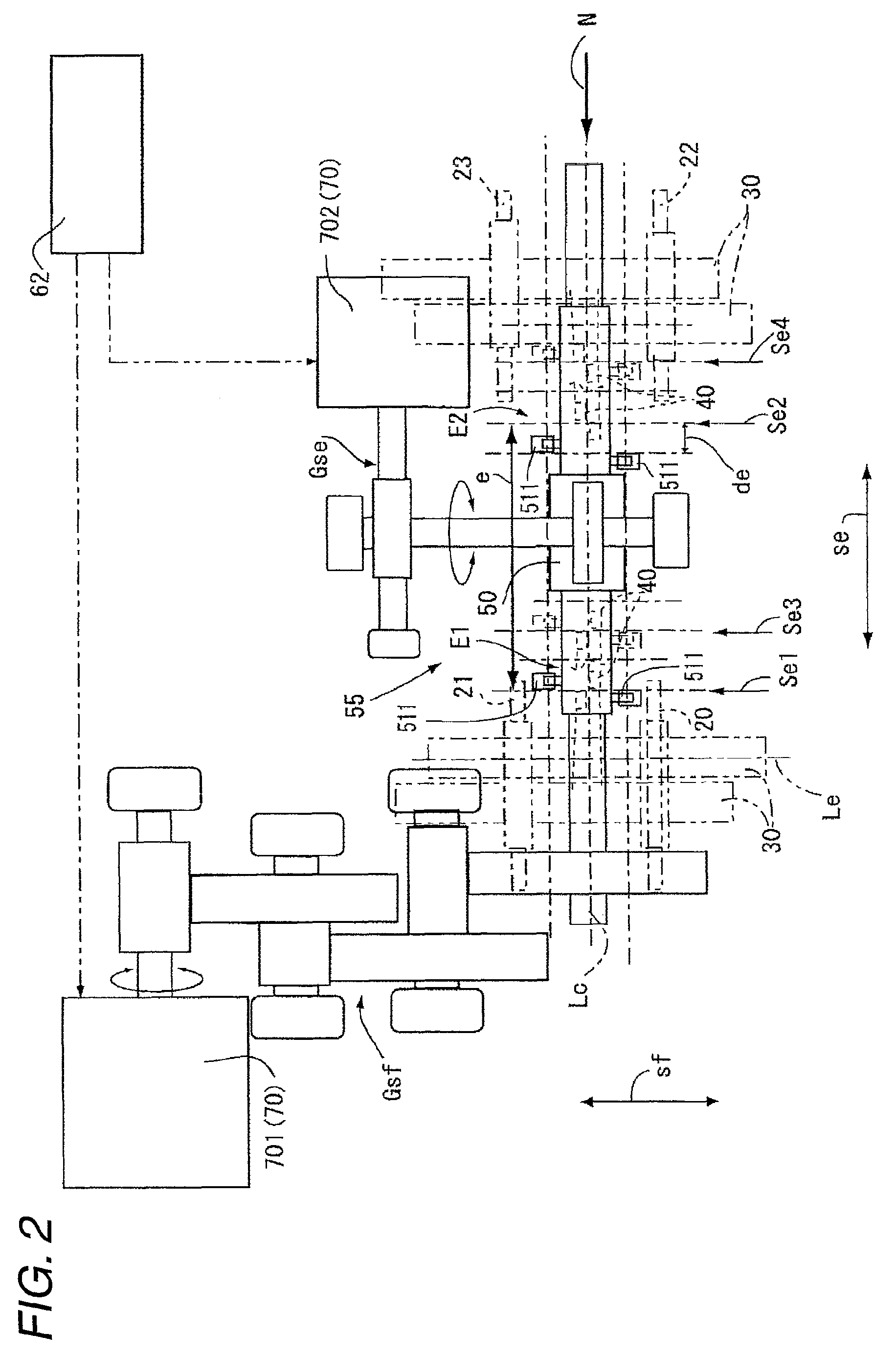
[0057]As shown in FIG. 2 and FIG. 3, the shift operation device of the automatic transmission 1 is provided with a shift operation member 55 (refer to FIG. 2) including a shaft portion 50 which extends in a select direction se and an actuator 70 on one end thereof is provided with a plurality of rails 30 axes of which extend in the shift direction sf orthogonal to the shaft portion 50. The shift operation device is also provided with the shift forks 20 to 23 which are integrally joined to the rails 30 to perform the shift operation of the gears 11, 12, 13, 14, 15, 16, 17 inside the automatic transmission 1, and ...
second embodiment
[0099]Next, a description will be given for a part of a second embodiment used in the shift operation device of the automatic transmission 1 of the present invention by referring to FIG. 9 to FIG. 12B.
[0100]In addition, the shift operation device of the second embodiment is similar in configuration to the first embodiment except that each of arm portions 51 which are arranged at the first and the second position E1, E2 inside a shift operation member 55 is formed into a single-shape member having one projection. Therefore, overlapping explanation will be omitted here.
[0101]As shown in FIG. 9, FIG. 10A and FIG. 10B, the arm portions 51 which are arranged at the first and the second positions E1, E2 on the shaft portion 50 and formed into a single-shape member are controlled for the position by an actuator 70a so as to be deviated by a predetermined amount h1 (refer to FIG. 10A) in the select direction se and also so as to be in contact with the one-side pressure receiving surface fp1...
PUM
 Abstract
Description
Claims
Application Information