Showcase

a technology for a display case and a display case, applied in the field of display cases, can solve the problems of heat loss, inability to heat the inside of the display case, and heat load produced in the display case, so as to improve the maintenance efficiency, improve the appearance and impression of the whole showcase, and make the top of the display case wider

Inactive Publication Date: 2011-12-06
SANYO ELECTRIC CO LTD
View PDF6 Cites 11 Cited by
  • Summary
  • Abstract
  • Description
  • Claims
  • Application Information

AI Technical Summary

Benefits of technology

According to the first aspect of the invention, there is provided a showcase in which the inside of a display chamber formed in a main body thereof is illuminated with an illumination apparatus, the illumination apparatus including: a plurality of LED illumination components equipped with LED elements; a holding member attached to the main body to hold the LED illumination components; a wiring connector provided between the LED illumination components; and a reflecting plate covering the connector. In consequence, the connector can be hidden by the reflecting plate, and the appearance can be improved.
Moreover, the light from the LED elements diffusely reflected in the holding member can be further reflected toward the outside, and the inside of the display chamber can be more effectively illuminated.
Thus, when, for example, a plurality of shelves are put up in the display chamber, the top and inner part of the shelf on the uppermost stage can be more brightly illuminated. Floating-like illumination effects can improve the appearance and impression of the whole showcase, and can also make the top of the display chamber look wider.
According to the third aspect of the invention, in addition to the above aspect, the showcase comprises an attachment member attached to the ceiling of the display chamber, wherein the holding member is attached to the attachment member in a removably engaged manner. In consequence, the LED illumination component can be easily attached to the ceiling of the display chamber. The attachment / detachment of the illumination apparatus itself is easy, and the efficiency of maintenance is therefore improved.

Problems solved by technology

This is a disadvantage in that heat load is produced in the display chamber due to the illumination with the fluorescent lamps.
Heat loss is produced at this point, which disadvantageously causes the inside of the display chamber to be heated not only by the fluorescent lamp itself but also by the radiant heat of the fluorescent lamp.
This disadvantageously increases running costs.
Another disadvantage is that ultraviolet rays falling on commodities displayed in the display chamber have an adverse effect on the commodities.
Still another disadvantage is that the fluorescent lamp uses an alternating current and has the problem of flickering, and thus has an adverse effect on the eyes.
Moreover, the fluorescent lamp has to be replaced when a luminance decrease or lighting defect is caused by deterioration over time.
This forces a user to replace the fluorescent lamp, which is unfortunately a troublesome work.
Furthermore, the fluorescent lamp contains mercury, which disadvantageously prevents the used fluorescent lamp from being easily discarded.
Thus, the wiring connector is visible to the outside through the shade, which disadvantageously impairs the appearance.
Moreover, the wiring connector is disposed in the vicinity of the LED element, so that light radiated from the LED element is blocked by the wiring connector.
This disadvantageously prevents the inside of the display chamber from being effectively illuminated.
It is therefore disadvantageous that if light of the LED element is blocked by, for example, commodities placed on the shelf, the light does not reach farther, so that it is dark in the inner part of the display chamber and the effects of illumination decrease.
Therefore, even if an LED illumination component enabling a predetermined intensity of illumination is provided in the canopy, it is unfortunately impossible to effectively illuminate the inside of the display chamber, particularly, the inner upper part of the display chamber.

Method used


Image

  • Showcase
  • Showcase
  • Showcase

Examples


Embodiment Construction

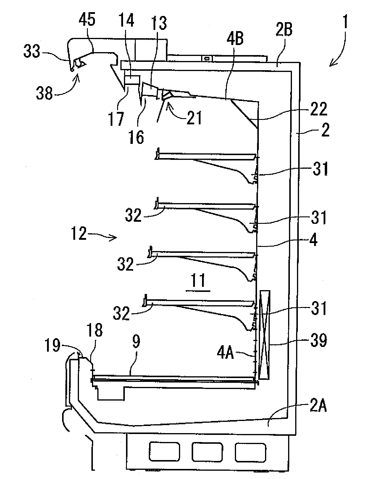
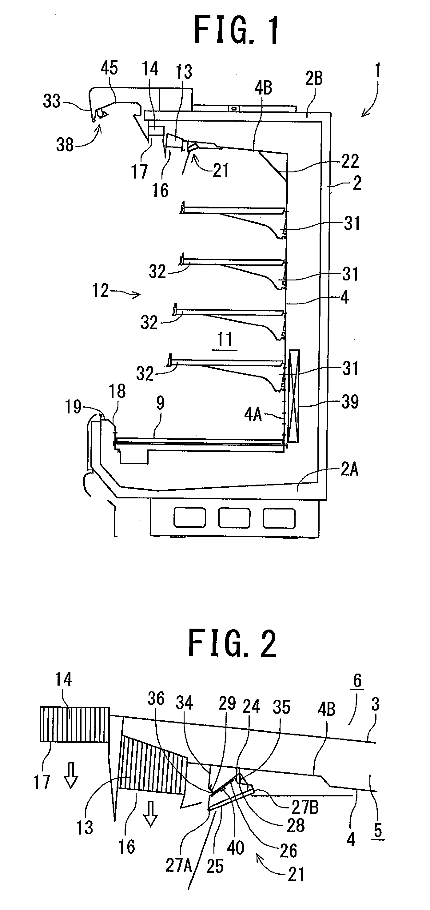
Embodiments of the present invention will hereinafter be described with reference to the drawings. FIG. 1 shows a longitudinal sectional side view of a showcase 1 to which the present invention is applied. FIG. 2 shows a partially enlarged view of FIG. 1. The showcase 1 is a vertical open showcase installed in, for example, a store such as a supermarket. The main body of the showcase 1 is composed of an insulating wall 2 substantially U-shaped in section and having a front opening, and unshown insulating side plates attached to the side surfaces of the insulating wall 2 at an installation site.

A partition plate 4 and another partition plate 3 (only shown in FIG. 2) are attached to the inside of the insulating wall 2 of the showcase 1 with a space therebetween. Two layers of inner and outer ducts 5, 6 (only shown in FIG. 2) are formed between the partition plate 4, etc. and the insulating wall 2. A bottom plate 9 is attached to the front of the lower edge of a rear partition plate 4A...


PUM


Abstract

An object is to provide a showcase capable of improving the appearance of an illumination apparatus and also capable of improving the effects of illumination by the illumination apparatus. In the showcase, the inside of a display chamber formed in a main body thereof is illuminated with the illumination apparatus. The illumination apparatus includes: a plurality of LED illumination components equipped with LED elements; a holding member attached to the main body to hold the LED illumination components; a wiring connector provided between the LED illumination components; and a reflecting plate covering the connector.

Description

BACKGROUND OF THE INVENTIONThe present invention relates to a showcase in which the inside of a display chamber formed in the main body thereof is illuminated with an illumination apparatus.Conventional showcases of the above-mentioned type include an open showcase as shown in, for example, Patent Document 1. In such an open showcase, cold air is discharged from an outlet formed at the lower edge of an opening in an insulating wall substantially U-shaped in section toward an inlet at the lower edge of the opening, thereby forming a cold air curtain at the opening. Thus, the inside of a display chamber enclosed by the insulating wall is cooled at a predetermined temperature. Further, a plurality of fluorescent lamps are attached to, for example, a canopy located outside the upper edge of the opening, to both side edges of the openings and to the lower surface of the front of a shelf in order to illuminate the inside of the display chamber and the showcase itself (e.g., see Japanese P...

Claims


Application Information

Patent Timeline
Patent Type & Authority Patents(United States)
IPC IPC(8): F25D27/00A47F11/10
CPCA47F3/001A47F11/10F21W2131/405F21Y2101/02F21Y2115/10A47F3/04
Inventor OTSUKI, ATSUOAMARI, YOICHIOKETANI, TETSUYASHIBUSAWA, SAKUMI
Owner SANYO ELECTRIC CO LTD
Why Eureka
Try Eureka