Electrical connector with improved contact structure

a technology of contact structure and electric connector, which is applied in the direction of coupling device connection, two-part coupling device, electrical apparatus, etc., can solve the problems of high assembly time and inability to reduce the cost of mold manufacturing easily

Inactive Publication Date: 2011-12-06
HON HAI PRECISION IND CO LTD
View PDF4 Cites 24 Cited by
  • Summary
  • Abstract
  • Description
  • Claims
  • Application Information

AI Technical Summary

Problems solved by technology

It needs much time to be assembled, and the cost of mold manufacture can not be decreased easily.

Method used


Image

  • Electrical connector with improved contact structure
  • Electrical connector with improved contact structure
  • Electrical connector with improved contact structure

Examples


Embodiment Construction

In the following description, numerous specific details are set forth to provide a thorough understanding of the present invention. However, it will be obvious to those skilled in the art that the present invention may be practiced without such specific details. In other instances, well-known circuits have been shown in block diagram form in order not to obscure the present invention in unnecessary detail. For the most part, details concerning timing considerations and the like have been omitted inasmuch as such details are not necessary to obtain a complete understanding of the present invention and are within the skills of persons of ordinary skill in the relevant art.

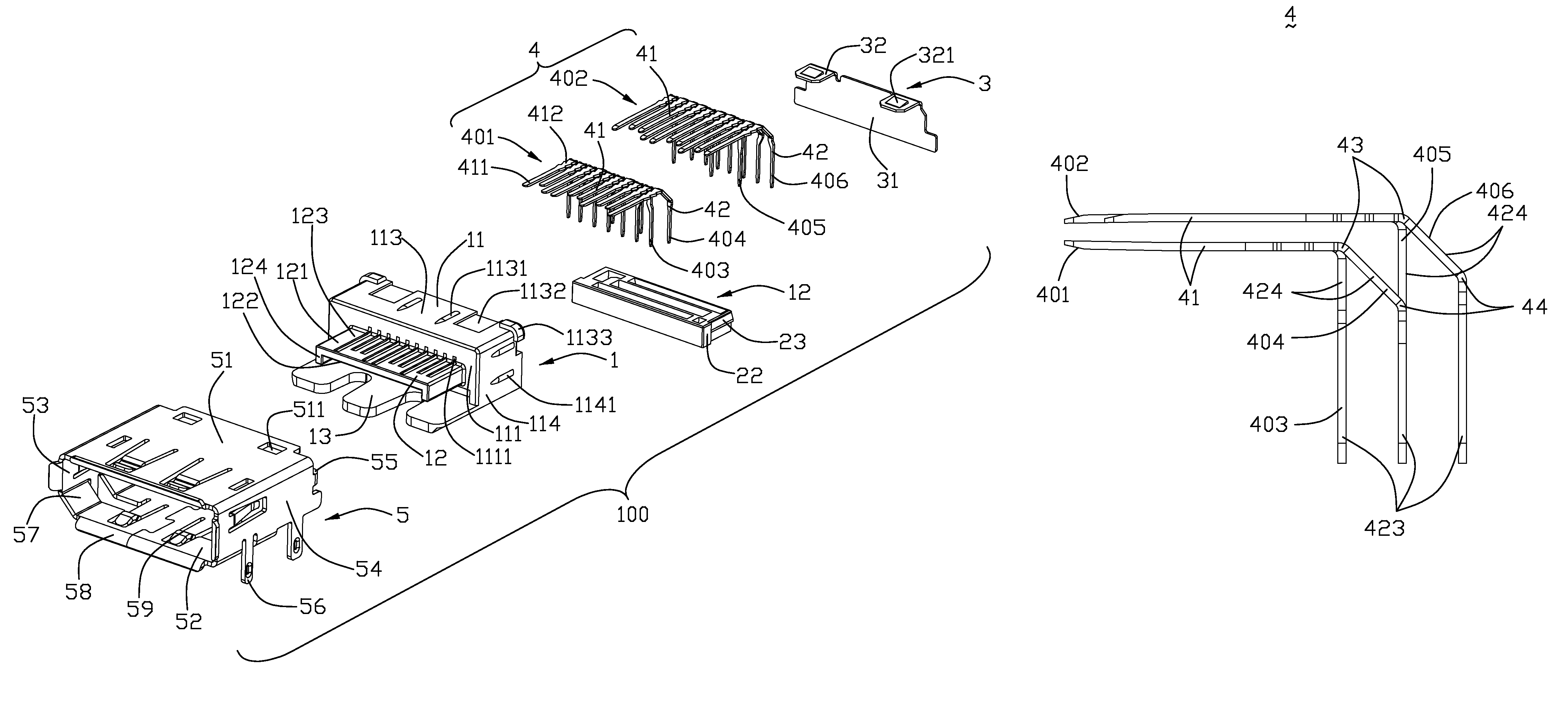
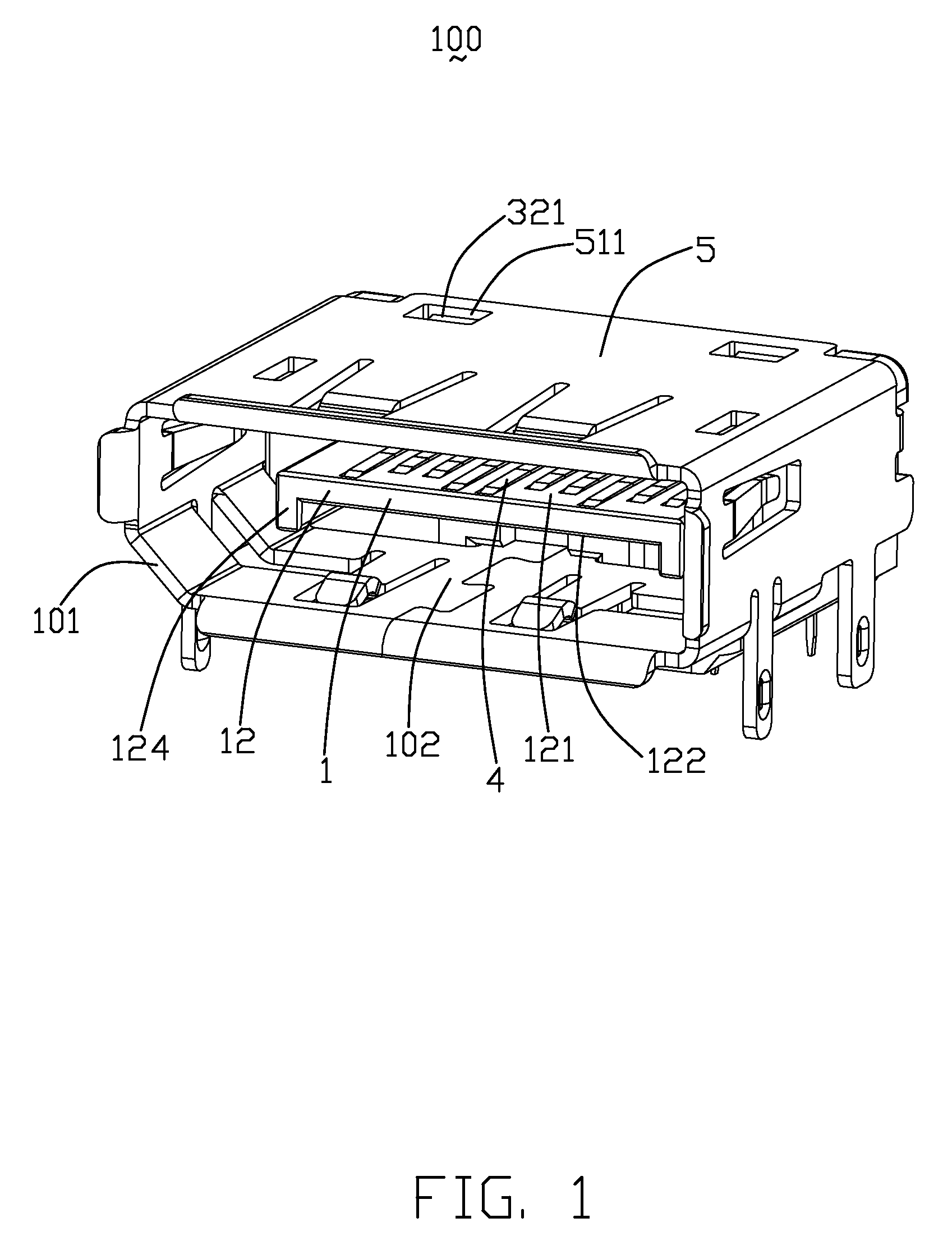
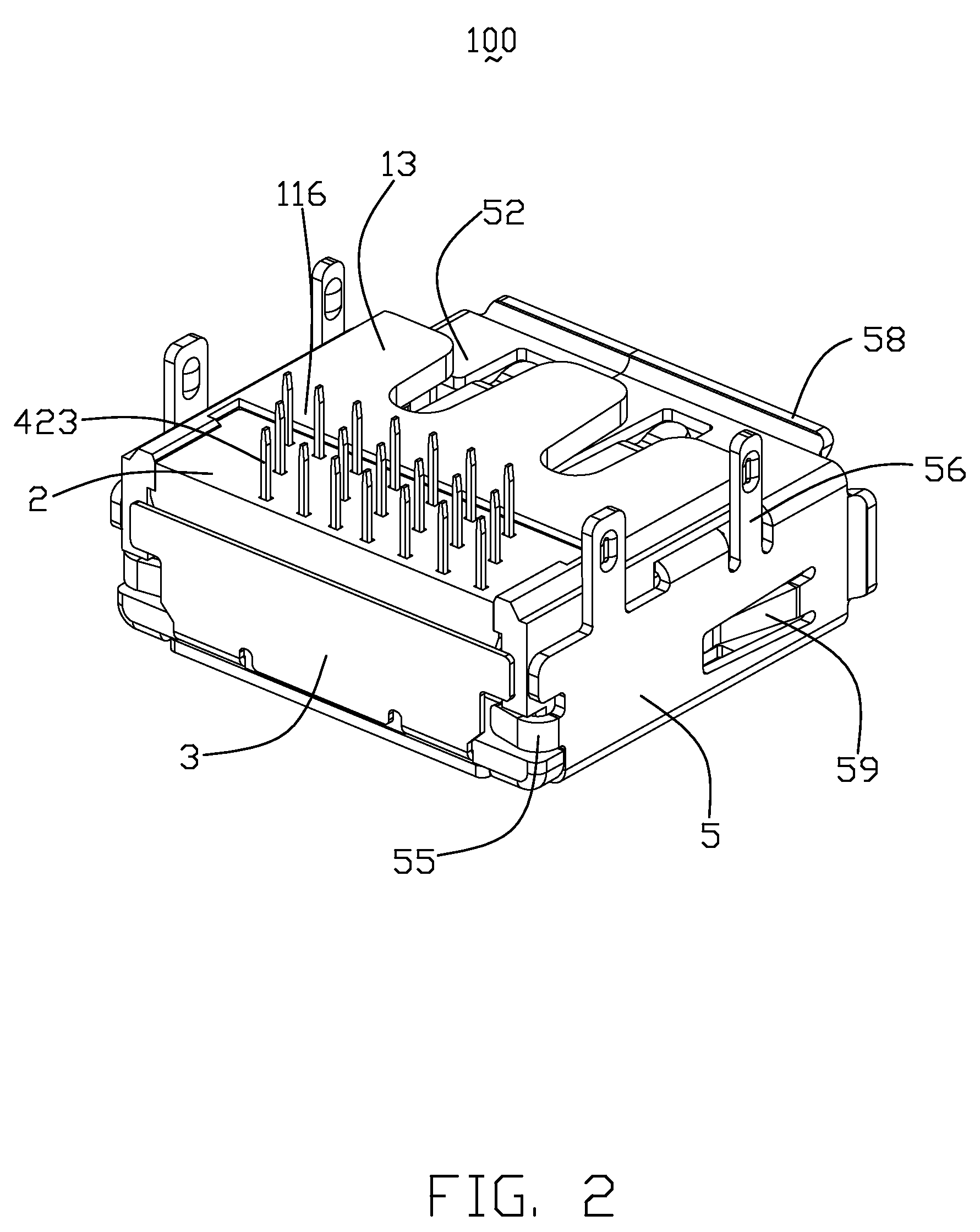
Referring to FIGS. 1-6, an electrical connector 100 according to the present invention is disclosed. The electrical connector 100 has a mating face 101 and an inserting port 102 extending inwardly from the mating face 101 for receiving a corresponding plug (not shown). The electrical connector 100 comprises an insula...


PUM


Abstract

An electrical connector (100) having an inserting port (102) for receiving a corresponding plug, includes an insulative housing (1) and a plurality of contacts (4) retained in the insulative housing (1). Each contact (4) has a first portion (41) extending horizontally into the inserting port (102), a first bending portion (43) bending downwardly from a rear end of the first portion (41), and a second portion (42) extending downwardly from the first bending portion (43). The contacts (4) are arranged in two groups. The first portions (41) of each contact group (401, 402) are arranged in a row along a transverse direction respectively. The second portions (42) in each contact group (401, 402) are arranged in at least two rows along a front-to-back direction respectively. The first bending portions (43) of the contacts (4) in each contact group are arranged in a line along the transverse direction respectively.

Description

BACKGROUND OF THE INVENTION1. Field of the InventionThe present invention relates to an electrical connector, and more particularly to electrical connectors with improved contact structure.2. Description of Related ArtElectrical connectors with high transmitting speed, such as HDMI (High-Definition Multimedia Interface), Displayport etc, are widely used on TVs, computers, etc. Such an electrical connector usually includes an insulative housing and a plurality of differential signal contacts and grounding contacts retained in the insulative housing. The insulative housing has a base portion and a tongue extending forwardly from the base portion. The contacts are arranged in two groups which comprise a first contact group retained on an upper side of the tongue and a second contact group retained on a lower side of the tongue. Each contact has a contact portion extending to the tongue and a tail portion bending perpendicularly downwardly from the contact portion.The first and second c...

Claims


Application Information

Patent Timeline
Patent Type & Authority Patents(United States)
IPC IPC(8): H01R24/00H01R12/55
CPCH01R12/725H01R23/688
Inventor XIONG, FENGHAN, HONG-QIANGHU, LUN-SONGZHU, ZI-QIANG
Owner HON HAI PRECISION IND CO LTD
Why Eureka
Try Eureka