Hybrid femoral implant

a femoral implant and hybrid technology, applied in the field of femoral components, can solve the problems of difficult to see the seepage of bone cement, difficulty for surgeons to detect the presence of loose cement particles, etc., and achieve the effects of facilitating tissue in-growth, promoting tissue in-growth, and facilitating both the implantation and the possible removal of future materials

Active Publication Date: 2011-12-06
HOWMEDICA OSTEONICS CORP
View PDF50 Cites 65 Cited by
  • Summary
  • Abstract
  • Description
  • Claims
  • Application Information

AI Technical Summary

Benefits of technology

[0004]It is one aspect of the present invention to provide a hybrid femoral component for a knee replacement prosthesis that includes a combination of two or more different surface textures on the at least three and preferably five surfaces that contact the resected distal femur. Preferably, the two different surface textures can include surfaces for receiving bone cement and surfaces for promoting tissue in-growth. Such bone surfaces can come in many varieties including hydroxyapatite coated, waffle or porous beaded structures or a smooth surface for cement. Having both cement accepting surfaces and surfaces for promoting tissue in-growth on a single femoral component but in different areas eases both the implantation and the possible future removal of the implant.
[0006]It is another aspect of the present invention to eliminate the need for bone cement to be applied to the posterior region of the implant. It is often difficult for the surgeon to detect the presence of loose cement particles that flow out of the region between the implant and the resected knee during implantation of the implant onto the distal femur. When a femoral component is prepared for cement implantation, its inside surfaces (those contacting the bone) are covered with bone cement in an amount to ensure full area coverage of the bone cement onto the femoral component and distal femur. When this prepared component is impacted onto the bone, some bone cement may seep out which is then removed by the surgeon. However, it is difficult to see this bone cement seepage on the posterior aspect of the implant. This is especially true if a minimally invasive surgical procedure is utilized, which procedures limit the length of the incision made in the anterior femur. Thus eliminating the bone cement from the posterior and posterior chamfer surface, if present, eliminates the seepage problem in this area.
[0007]Using a hybrid femoral component design in which at least one in-growth surface is preferably used on the inner posterior surfaces of the implant also benefits a press-fit implantation when the bone cuts are not made perfectly. The bone cement in the anterior region of the implant will fill in any gaps that are present between the implant and the resected bone. This packed cement will help to ensure a press-fit between the implant and the resected bone in the posterior region of the implant.

Problems solved by technology

It is often difficult for the surgeon to detect the presence of loose cement particles that flow out of the region between the implant and the resected knee during implantation of the implant onto the distal femur.
However, it is difficult to see this bone cement seepage on the posterior aspect of the implant.

Method used


Image

  • Hybrid femoral implant
  • Hybrid femoral implant
  • Hybrid femoral implant

Examples


Embodiment Construction

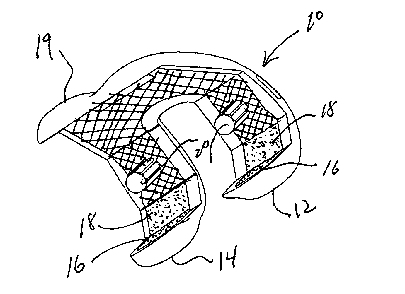
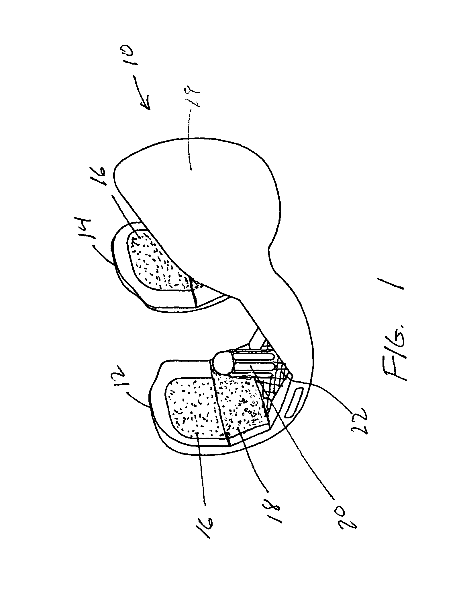
[0015]Referring to FIG. 1, there is shown the femoral component of the present invention generally denoted as 10 with anterior outer surface 19. The view shown is from the anterior medial side looking back toward the posterior condyles 12 and 14, respectively. As can be seen, the posterior condyles 12 and 14 include an inner posterior surface 16 and an inner posterior chamfer surface 18. Also shown is a fixation peg 20 which can be of any typical design. The distal surface 22 is also shown.

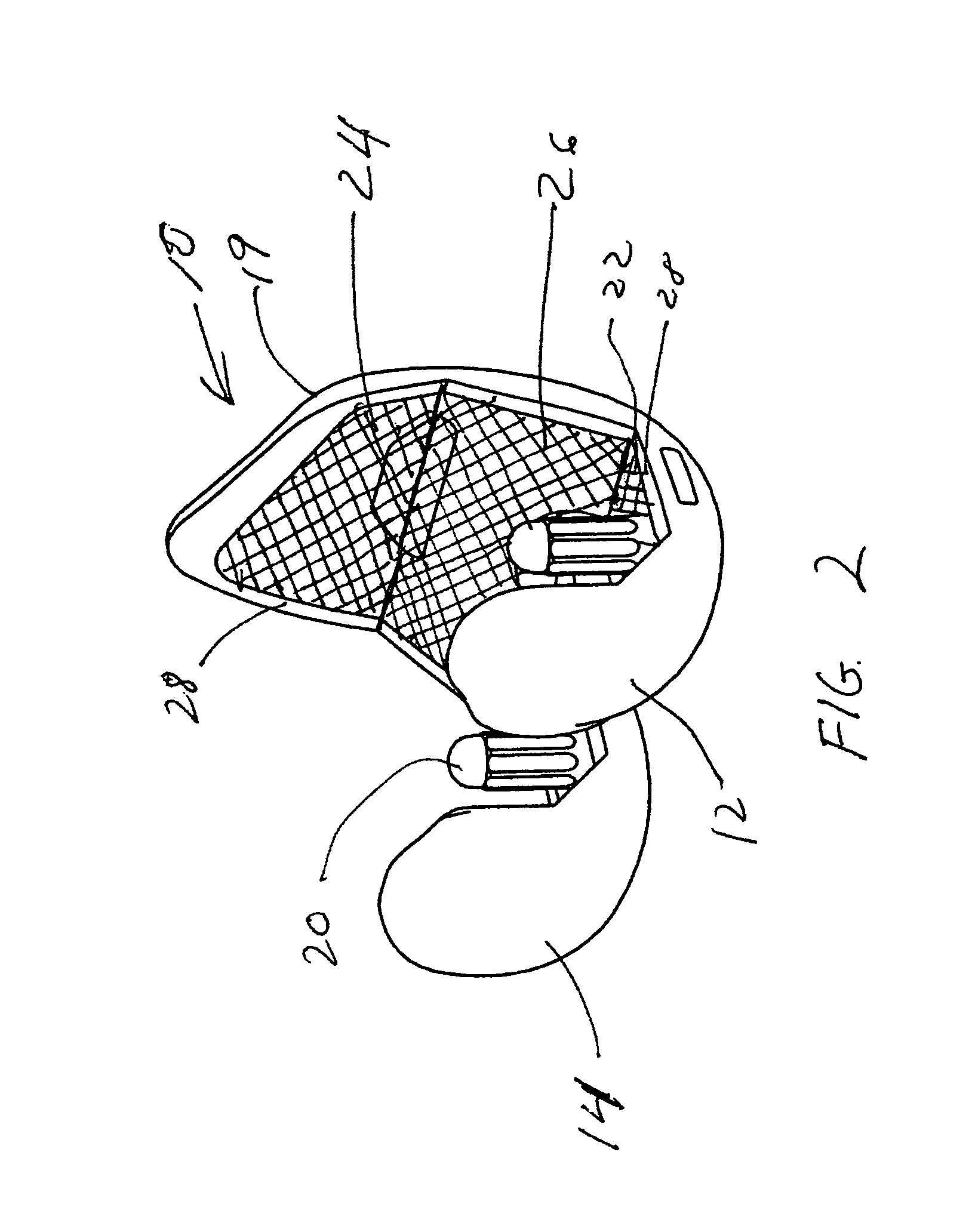
[0016]Referring to FIG. 2, there is shown an isometric view looking from the posterior medial side which shows the anterior inner surface 24 and the anterior chamfer surface 26 along with both posterior condyles 12 and 14. In this view, both the medial and lateral pegs 20 are shown. Preferably, surfaces 22, 24 and 26 have a waffle pattern and are preferably recessed slightly so that the waffle pattern does not extend above the edge surfaces 28 surrounding the anterior and anterior chamfer surfaces...


PUM

PropertyMeasurementUnit
structureaaaaaaaaaa
porous structureaaaaaaaaaa
surface texturesaaaaaaaaaa

Abstract

A hybrid prosthetic femoral component has an outer bearing surface for engaging a tibial bearing and an inner surface for engaging a prepared distal femur. The inner surface having a distal surface, an anterior surface and a posterior surface, wherein said posterior surface has a first surface structure for allowing tissue ingrowth and the anterior and distal surfaces having a second surface structure for contacting bone cement. The first and second structure have different surface characteristics with different properties wherein the first surface structure is a porous surface and the second surface is a non-porous textured surface. The hybrid prosthetic femoral component further comprises an anterior chamfered surface and a posterior chamfered surface wherein the posterior chamfered surface includes the first surface structure and the anterior chamfered surface includes the second surface structure.

Description

BACKGROUND OF THE INVENTION[0001]The present invention relates to an orthopedic implant, more particularly to a femoral component for a knee prosthesis. The femoral component has three inside surfaces opposite the bearing surface of the femoral component with at least a posterior surface of the femoral component having a porous coating for tissue in-growth.[0002]In order to treat arthritic knees with prosthetic knee implants surgeons have performed total knee arthroplasty (TKA) in which a tibial component, a femoral component and a patella component are implanted onto a surgically prepared tibia, femur and patella. With regard to the femoral component, typically at least three resected surfaces are formed on the distal femur. These surfaces are the posterior, distal and anterior surfaces of the femur. Typically these cuts are planar, although in some situations, the posterior surface may be rounded. In addition to the posterior, anterior and distal surfaces of the femur, two additio...

Claims


Application Information

Patent Timeline
Patent Type & Authority Patents(United States)
IPC IPC(8): A61F2/40
CPCA61F2/3859A61F2/30767A61F2002/30011A61F2002/30909A61F2250/0023A61F2310/00796B33Y80/00
Inventor ROGER, CHRISTOPHER ABEE
Owner HOWMEDICA OSTEONICS CORP
Why Eureka
Try Eureka