
Tissue protective system and method for thermoablative therapies

a tissue protective system and thermoablative therapy technology, applied in the field of balloon catheters, can solve the problems of gland ablation, increased risk of male impotency, injury or destruction of one eye, etc., and achieve the effect of protecting from possible removal or

Inactive Publication Date: 2008-09-18
CHINN DOUGLAS O
View PDF5 Cites 8 Cited by
  • Summary
  • Abstract
  • Description
  • Claims
  • Application Information

AI Technical Summary

Benefits of technology

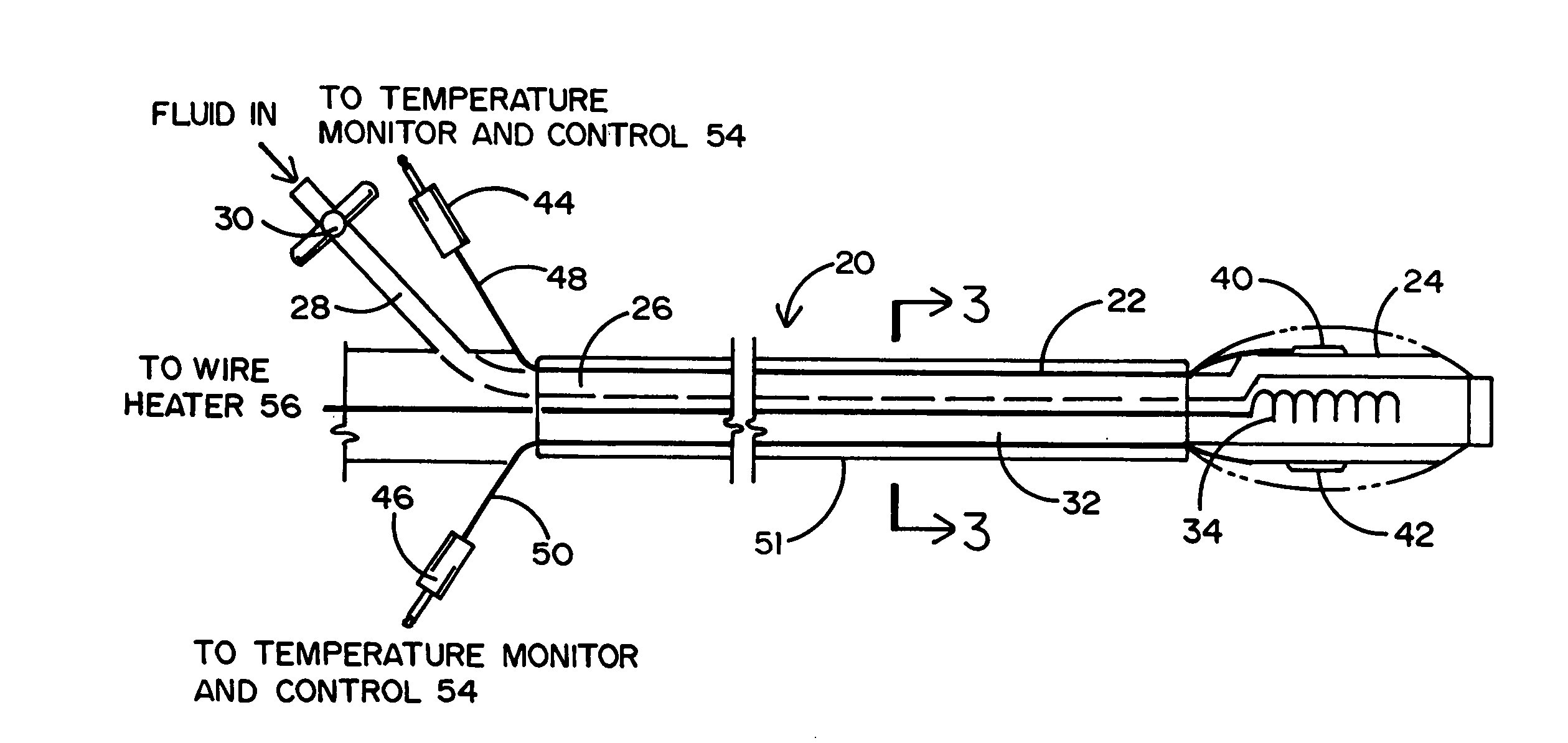
[0008]Briefly, and in general terms, disclosed herein are a tissue protecting and sparing method and a balloon catheter having particular application for use in the treatment of prostate (or other organ) cancer by means of thermoablative therapy. In those cases where a minimally invasive procedure is desirable, the prostate gland is either frozen or heated to a lethal temperature (e.g., by means of cryoablating the prostate with iceballs or by means of microwave, thermomagnetic radio frequency, or high frequency ultrasound treatments). According to the tissue sparing method of this invention, a balloon catheter is inserted in a channel that is formed between a patient's prostate to be treated and the neurovascular bundle (NVB) to be protected. When the balloon of the catheter is inflated, the patient's NVB is correspondingly lifted off and dissected from the prostate gland undergoing treatment. Thus, not only will the inflated balloon function as a thermal insulator and reflector of soundwaves, but the NVB will be spared from the lethal temperature to which the prostate gland is frozen or heated. In the alternative, the tissue sparing method of this invention can also be achieved by means of a sheath that is carried by a diamond tipped needle trocar. The trocar cuts an access channel through the patient's tissue and is then withdrawn leaving the sheath behind to provide separation and thermal isolation between the patient's prostate and the NVB. By virtue of the inflated balloon and the sheath, the NVB will be protected from possible removal or damage which has been known to result in the patient becoming sexually impotent.

Problems solved by technology

An undesirable side effect of total gland ablation is injury or destruction to one or both of the neurovascular bundles (NVBs) which run bilaterally on the surface of the gland in a posterior lateral position.
If such bundles are damaged, injured or accidentally removed during prostate cancer treatment, the risk of male impotency is increased.
This delay in diagnosis or avoidance of proper treatment can often lead to continued growth and advancement of the cancer until an incurable stage is reached.
If there is a large volume of cancer or the cancer appears to have penetrated through the capsule of the prostate gland, then destruction of the NVB often becomes necessary.
However, during the ablative surgical procedure, it is often difficult to dissect or otherwise lift the NVB off the gland which, consequently, results in an injured NVB.
In order to otherwise avoid injuring the NVBs during ablative therapy, a portion of the prostate gland may have to remain untreated, which potentially leaves some of the cancer behind.
Unfortunately, the conventional cryosurgical and heating techniques have proven to be flawed, such that the heating might be overcome by the freezing probes or be too strong and thereby damage the NVB by excess heat.
Once again, however, there is either too little cooling and the NVBs are damaged or destroyed or there is too much cooling and cancerous tissue may be left behind.
However, it has proven to be difficult to precisely control the heating and cooling down to the precise millimeters of the tissue requiring treatment.

Method used


Image

  • Tissue protective system and method for thermoablative therapies
  • Tissue protective system and method for thermoablative therapies
  • Tissue protective system and method for thermoablative therapies

Examples


Embodiment Construction

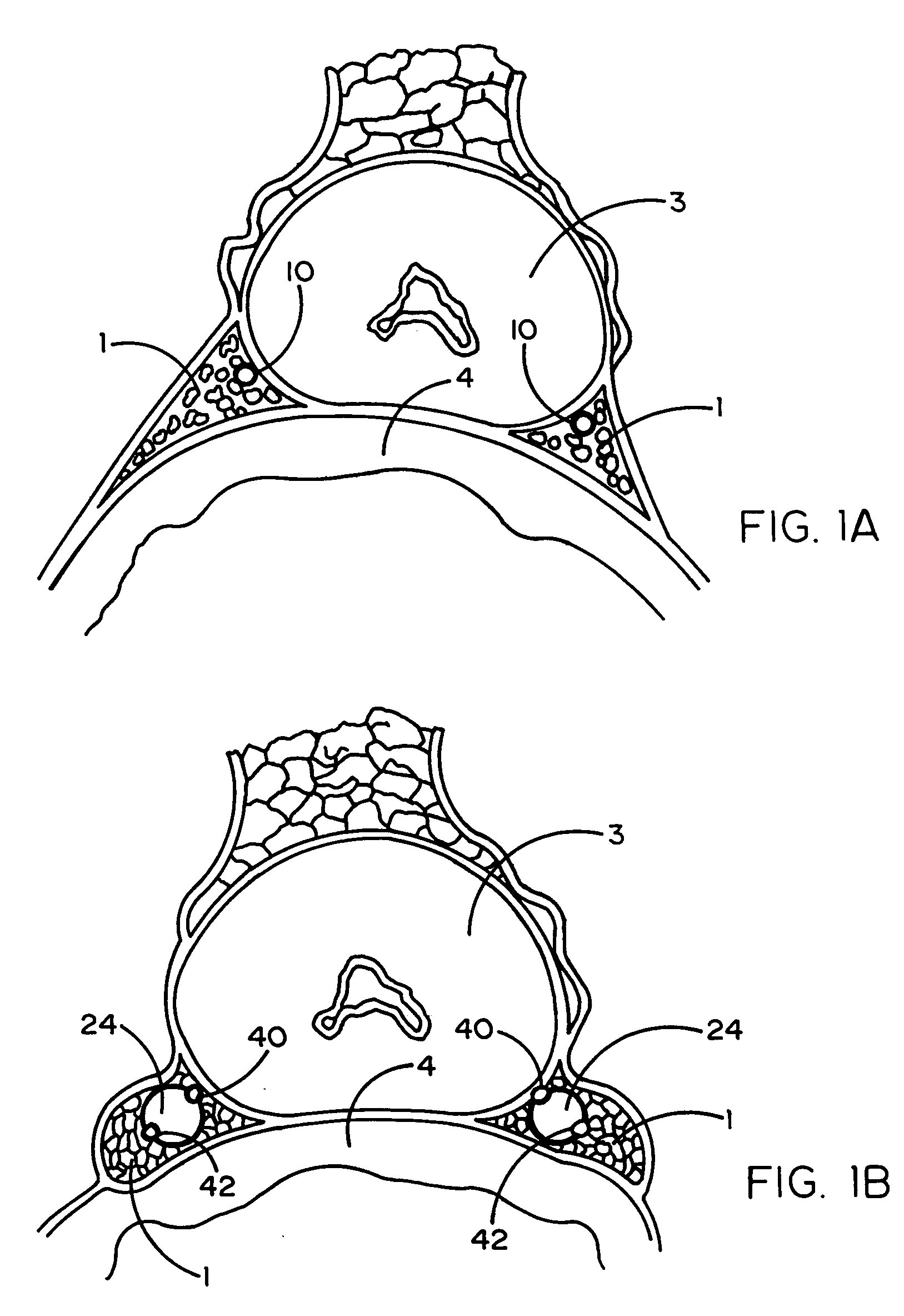
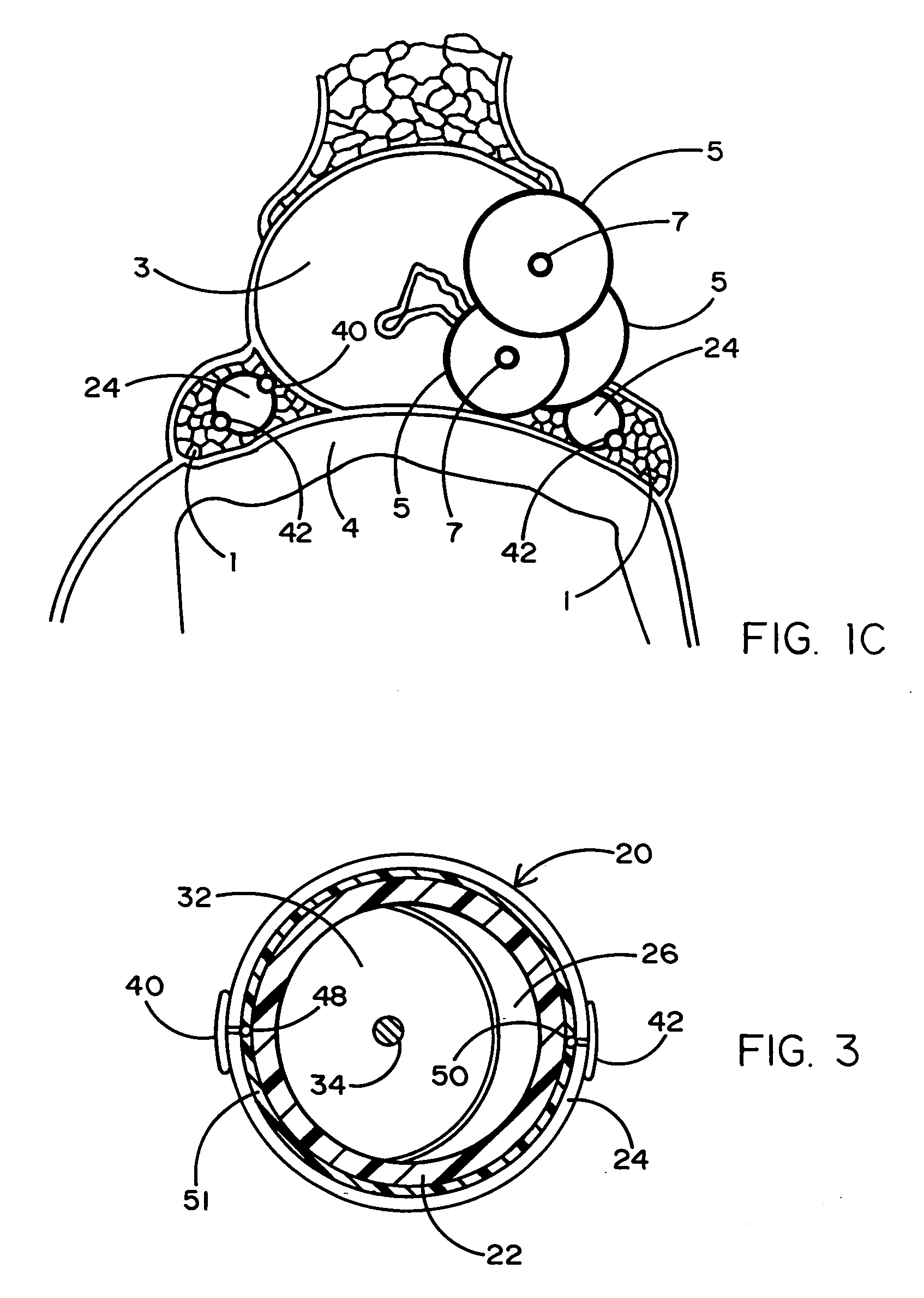
[0021]Referring to the drawings, a portion of the human anatomy is illustrated in FIG. 1A to show the neurovascular bundles (NVBs) 1 located above the rectum 4 and attached to opposite sides of the prostate gland 3 in need of treatment for cancer. In order to preserve the NVBs 1 during a thermoablative surgical procedure, they must be moved off or dissected from the prostate gland 3. As will be explained in greater detail hereinafter, and as an important improvement to conventional minimally invasive thermoablative techniques, unique balloon catheters (designated 20 and 20-1 in FIGS. 2 and 2A) have a balloon 24 that is inflated between each of the patient's NVBs 1 and the prostate gland 3 so as to elevate, separate and spare the NVB off the prostate. By preserving and sparing the NVBs 1, sexual potency of the patient can be maintained following surgery. That is, the patient could be made impotent if the NVBs were to be surgically removed or damaged during thermal (or mechanical) abl...


PUM


Abstract

A tissue protective system and method having particular application in thermoablative surgical therapies where heat or cold is used to create a kill zone for treating cancer cells as well as malignant or benign tumors in a targeted internal tissue area (e.g., the prostate) of a patient while sparing an adjacent benign internal tissue area (e.g., a neurovascular bundle). One of a hollow sheath or a balloon that is carried by a balloon catheter is located within an access opening that is made by a needle trocar inserted between the targeted tissue area in need of treatment and the benign tissue area to be protected in order to hold the protected tissue area off the targeted tissue area and away from the lethal temperature of the kill zone. The balloon of the balloon catheter is inflated in the access opening via a balloon channel which runs longitudinally through the catheter. At least one temperature sensor is mounted on the balloon and responsive to the temperature near the benign tissue area to be protected. Heat or cold is provided to the balloon from a heating wire or a circulating fluid, depending upon the temperature that is sensed by the temperature sensor.

Description

BACKGROUND OF THE INVENTION[0001]1. Field of the Invention[0002]This invention relates primarily to a balloon catheter associated with a temperature monitoring and control device and being adapted to protect (e.g., dissect, insulate, heat or cool) a defined internal tissue area to be spared that is located adjacent to a targeted internal tissue area which undergoes minimally invasive thermoablative therapy.[0003]2. Background Art[0004]In the treatment of benign and malignant conditions, minimally invasive therapies have been used in the past and are currently being developed today. These therapies are usually thermoablative in nature and include cryosurgery, high frequency ultrasound, thermomagnetic, microwave, and radio frequency therapies. Newly developed thermoablative therapies typically require a percutaneous access to an internal area of the body requiring treatment. Such percutaneous access is guided by imaging technology, i.e., CT scan, MRI, X-ray, ultrasound and other devel...

Claims


Application Information

Patent Timeline
Patent Type & Authority Applications(United States)
IPC IPC(8): A61B18/04A61B18/18A61F7/00A61F7/12
CPCA61B18/04A61B19/40A61B2018/046A61B2017/00274A61B2018/00547A61B2017/00084A61B90/04
Inventor CHINN, DOUGLAS O.
Owner CHINN DOUGLAS O
Learn More