AI technical title is built by Patsnap AI team. It summarizes the technical point description of the patent document.
a ball-and-socket joint, prosthetic technology, applied in the field of medical implants, can solve the problems of accelerated wear, implant damage, and achieve the effect of avoiding tissue inflammation and harm, accelerating wear, and reducing the risk of infection
Active Publication Date: 2011-12-06
BIOMEDFLEX
View PDF342 Cites 38 Cited by
Summary
Abstract
Description
Claims
Application Information
AI Technical Summary
This helps you quickly interpret patents by identifying the three key elements:
Problems solved by technology
Method used
Benefits of technology
Problems solved by technology
The problem with this type of configuration is the polymer eventually begins to degrade due to the caustic nature of blood, the high impact load, and high number of load cycles.
As the resilient member degrades, pieces of polymer may be liberated into the joint area, often causing accelerated wear, implant damage, and tissue inflammation and harm.
Implant replacement is undesirable from a cost, inconvenience, patient health, and resource consumption standpoint.
Implants using two hard elements of conventional design will be, however, subject to rapid wear.
First, a joint having one hard, rigid element on another will not be perfectly shaped to a nominal geometry.
Such imperfections will result in points of high stress, thus causing localized wear.
Furthermore, two hard elements would lack the resilient nature of a natural joint.
Some cyclical load in these areas stimulates bone growth and strength; however, excessive loads or shock stress or impulse loading the bone-to-implant interface will result in localized bone mass loss, inflammation, and reduced support.
Method used
Image
Click on the blue label to locate the original text in one second.
Reading with bidirectional positioning of images and text.
Examples
Embodiment Construction
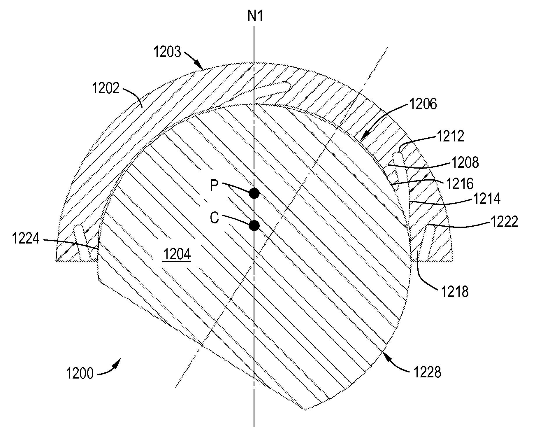
[0063]The present invention provides a specialized implant contact interface (implant geometry). In this geometry, an implanted joint includes two typically hard (i.e. metal or ceramic) members; however, at least one of the members is formed such that it has the characteristics of a resilient member, such as: the ability to absorb an impact load; the ability to absorb high cycle loading; the ability to be self-cleaning; and the ability to function as a hydrodynamic and / or hydrostatic bearing.
[0064]Generally, the contact resilient member is flexible enough to allow elastic deformation and avoid localized load increases, but not so flexible as to risk plastic deformation, cracking and failure. In particular, the resilient member is designed such that the stress levels therein will be below the high-cycle fatigue endurance limit. As an example, the resilient member might be only about 10% to about 20% as stiff as a comparable solid member. It is also possible to construct the resilient...
PUM
Property
Measurement
Unit
porosity
aaaaa
aaaaa
thickness
aaaaa
aaaaa
diameter
aaaaa
aaaaa
Abstract
A prosthetic joint includes: (a) first member having a balanced centroidal axis, and comprising a rigid material and a concave interior defining a cup surface, the cup surface including: (i) a cantilevered first flange defining a wear-resistant protruding first contact rim, the first flange being asymmetric relative to the balanced centroidal axis; and (ii) a cantilevered second flange defining a wear-resistant protruding second contact rim; (b) a second member comprising a rigid material with a wear-resistant, convex contact surface; (c) where the first and second contact rims bear against the contact surface of the second member, to transfer loads between the first and second members, while allowing pivoting motion therebetween; and (d) wherein the flanges are shaped and sized so as to deform elastically and permit the first and second contact rims to conform in an irregular shape to the contact surface, when the joint is under load.
Description
CROSS-REFERENCE TO RELATED APPLICATIONS[0001]This application is a Continuation-in-Part of application Ser. No. 12 / 826,620, filed Jun. 29, 2010, now U.S. Pat. No. 7,914,580, which is a Continuation-in-Part of application Ser. No. 12 / 714,288, filed Feb. 26, 2010, now U.S. Pat. No. 7,905,919 issued Mar. 15, 2011, which is a Continuation-in-Part of application Ser. No. 11 / 936,601, filed Nov. 7, 2007, currently pending, which claims the benefit of Provisional Patent Application 60 / 864,667, filed Nov. 7, 2006.BACKGROUND OF THE INVENTION[0002]This invention relates generally to medical implants, and more particularly to prosthetic joints having conformal geometries and wear resistant properties.[0003]Medical implants, such as knee, hip, and spine orthopedic replacement joints and other joints and implants have previously consisted primarily of a hard metal motion element that engages a polymer contact pad. This has usually been a high density high wear resistant polymer, for example Ultra...
Claims
Application Information
Patent Timeline
Application Date:The date an application was filed.
Publication Date:The date a patent or application was officially published.
First Publication Date:The earliest publication date of a patent with the same application number.
Issue Date:Publication date of the patent grant document.
PCT Entry Date:The Entry date of PCT National Phase.
Estimated Expiry Date:The statutory expiry date of a patent right according to the Patent Law, and it is the longest term of protection that the patent right can achieve without the termination of the patent right due to other reasons(Term extension factor has been taken into account ).
Invalid Date:Actual expiry date is based on effective date or publication date of legal transaction data of invalid patent.

