Highly wear resistant diamond insert with improved transition structure
a transition structure and diamond technology, applied in the field of polycrystalline diamond enhanced inserts, can solve the problems of reducing the hard limiting the flexibility of being able to provide pcd coatings with desired levels of hardness and toughness, and reducing the toughness of pcd material, so as to achieve the effect of small grain siz
Active Publication Date: 2011-02-10
SMITH INT INC
View PDF90 Cites 83 Cited by
- Summary
- Abstract
- Description
- Claims
- Application Information
AI Technical Summary
Benefits of technology
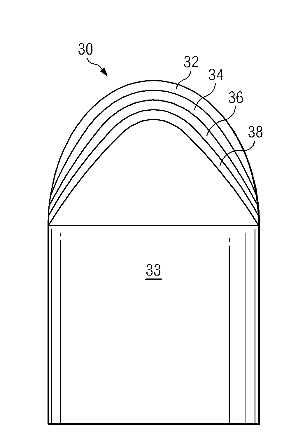
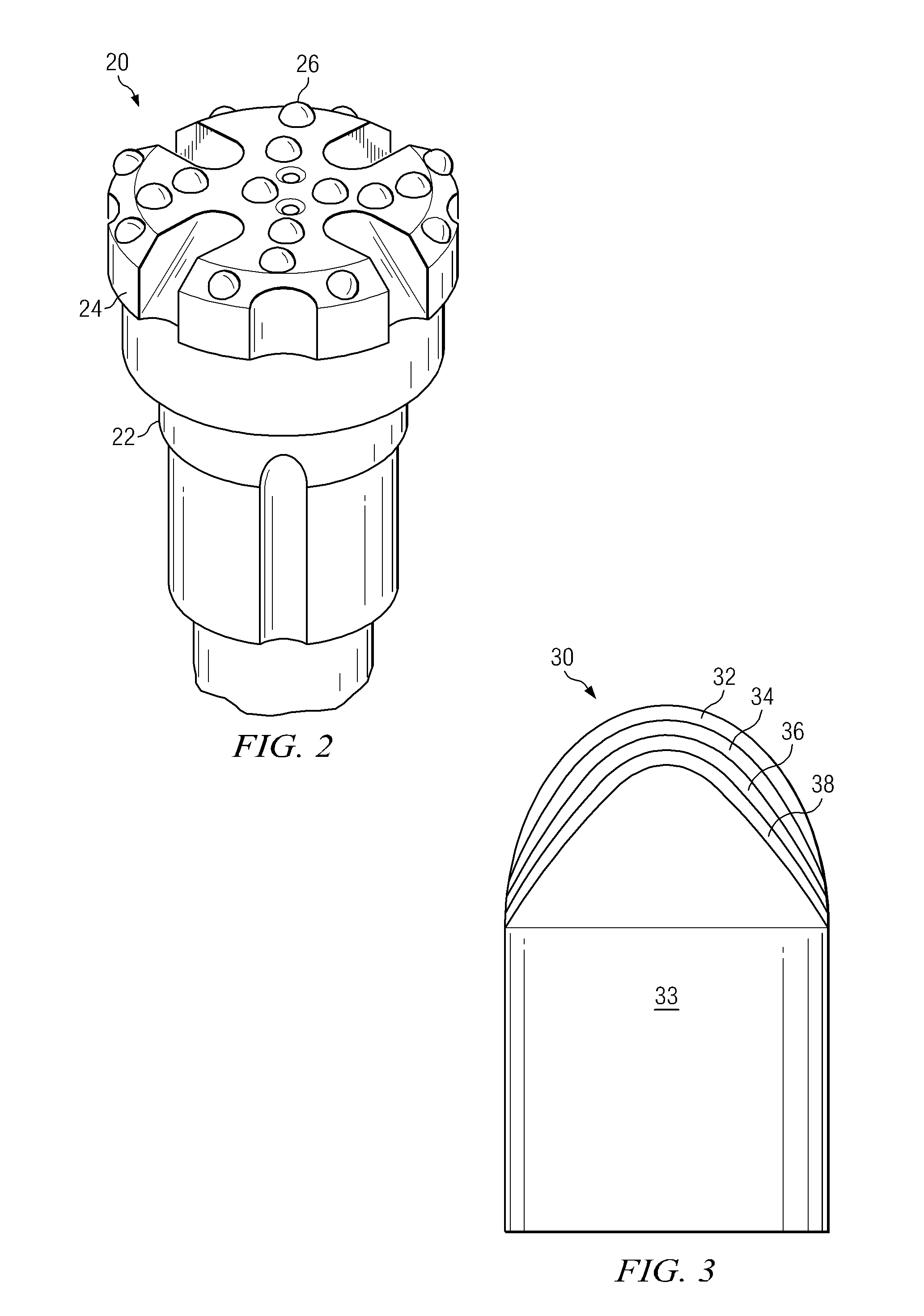
The patent text describes an insert for a drill bit that includes a metallic carbide body and an outer layer of polycrystalline diamond material. The polycrystalline diamond material is made up of interconnected first diamond grains and a first binder material. The insert also includes at least one transition layer between the metallic carbide body and the outer layer, which is made of second diamond grains, first metal carbide particles, and a second binder material. The second diamond grains have a larger grain size than the first diamond grains. The technical effect of this design is that the insert has improved wear resistance and can withstand higher temperatures during drilling operations.
Problems solved by technology
However, while higher metal content typically increases the toughness of the resulting PCD material, higher metal content also decreases the PCD material hardness, thus limiting the flexibility of being able to provide PCD coatings having desired levels of both hardness and toughness.
Additionally, when variables are selected to increase the hardness of the PCD material, typically brittleness also increases, thereby reducing the toughness of the PCD material.
Although the polycrystalline diamond layer is extremely hard and wear resistant, a polycrystalline diamond enhanced insert may still fail during normal operation.
Excessively high contact stresses and high temperatures, along with a very hostile downhole environment, also tend to cause severe wear to the diamond layer.
Lastly, the impact mechanism involves the sudden propagation of a surface crack or internal flaw initiated on the PCD layer, into the material below the PCD layer until the crack length is sufficient for spalling, chipping, or catastrophic failure of the enhanced insert.
External loads due to contact tend to cause failures such as fracture, spalling, and chipping of the diamond layer.
Internal stresses, for example thermal residual stresses resulting from the manufacturing process, tend to cause delamination between the diamond layer and the substrate or the transition layer, either by cracks initiating along the interface and propagating outward, or by cracks initiating in the diamond layer surface and propagating catastrophically along the interface.
However, the increase in diamond volume result in an increase in the magnitude of residual stresses formed on the diamond / substrate interface that foster delamination.
During cool-down after the diamond bodies to the substrate, the diamond contracts a smaller amount than the carbide substrate, resulting in residual stresses on the diamond / substrate interface.
Nevertheless, basic failure modes still remain.
These failure modes involve complex combinations of three mechanisms, including wear of the PCD, surface initiated fatigue crack growth, and impact-initiated failure.
Method used
View moreImage
Smart ImageViewing Examples
Examples
example 1
[0056]
LayerAvg grain size (μm)Binder % volWC % volouter2-8 ≧3second5-15>515-35third5-15>535-60fourth5-15>560-80
example 2
[0057]
LayerAvg grain size (μm)Binder % volWC % volouter4-8≧3second 8-12>515-35third10-15>535-55fourth12-20>555-75
example 3
[0058]
LayerAvg grain size (μm)Binder % volWC % volouter2-8 ≧3second4-8 >515-35third5-15>535-60fourth5-15>560-80
Login to View More PUM
| Property | Measurement | Unit |
|---|---|---|
| grain size | aaaaa | aaaaa |
| grain size | aaaaa | aaaaa |
| grain size | aaaaa | aaaaa |
Abstract
An insert for a drill bit may include a metallic carbide body; an outer layer of polycrystalline diamond material on the outermost end of the insert, the polycrystalline diamond material comprising a plurality of interconnected first diamond grains and a first binder material in interstitial regions between the interconnected first diamond grains; and at least one transition layer between the metallic carbide body and the outer layer, the at least one transition layer comprising a composite of second diamond grains, first metal carbide particles, and a second binder material, wherein the second diamond grains have a larger grain size than the first diamond grains.
Description
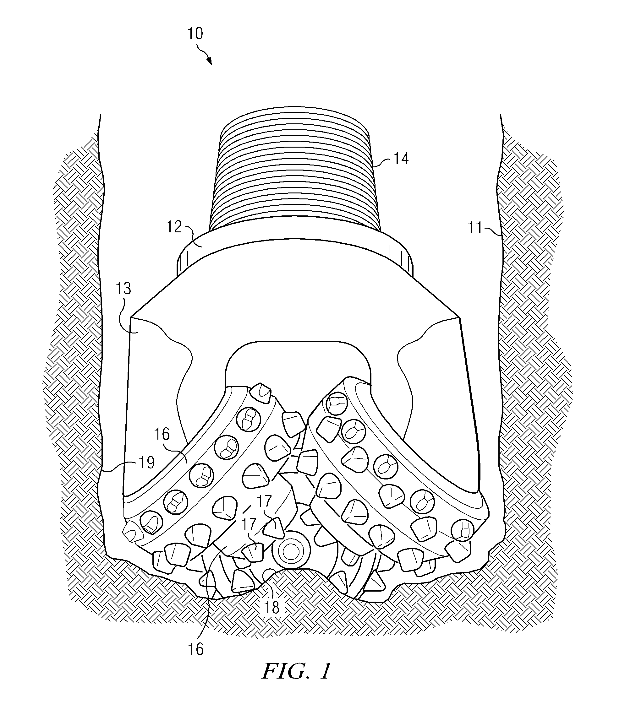
CROSS-REFERENCE TO RELATED APPLICATIONS[0001]This application claims priority to U.S. Patent Application No. 61 / 232,125, filed on Aug. 7, 2009, the contents of which are herein incorporated by reference in their entirety.BACKGROUND OF INVENTION[0002]1. Field of the Invention[0003]Embodiments disclosed herein relate generally to polycrystalline diamond enhanced inserts for use in drill bits, such as roller cone bits and hammer bits, in particular. More specifically, the invention relates to polycrystalline diamond enhanced inserts having an outer layer and at least one transition layer.[0004]2. Background Art[0005]In a typical drilling operation, a drill bit is rotated while being advanced into a soil or rock formation. The formation is cut by cutting elements on the drill bit, and the cuttings are flushed from the borehole by the circulation of drilling fluid that is pumped down through the drill string and flows back toward the top of the borehole in the annulus between the drill s...
Claims
Login to View More Application Information
Patent Timeline
 Patent Type & Authority Applications(United States)
IPC IPC(8): E21B10/46
CPCC22C26/00C22C2204/00E21B10/567E21B10/36E21B10/5673B22F2207/13E21B10/55B22F2207/01E21B10/5735C22C2026/006C22C2026/008E21B10/52E21B10/60
Inventor MOURIK, NEPHI A.CARIVEAU, PETERBELLIN, FEDERICOFANG, YI
Owner SMITH INT INC
Features
- R&D
- Intellectual Property
- Life Sciences
- Materials
- Tech Scout
- Unparalleled Data Quality
- Higher Quality Content
- 60% Fewer Hallucinations
Learn More Browse by: Latest US Patents, China's latest patents, Technical Efficacy Thesaurus, Application Domain, Technology Topic, Popular Technical Reports.
© 2025 PatSnap. All rights reserved.Legal|Privacy policy|Modern Slavery Act Transparency Statement|Sitemap|About US| Contact US: help@patsnap.com


