Laser based metal deposition of implant structures

a technology of implant structure and metal deposition, which is applied in the direction of dental implants, solid-state diffusion coatings, elbow joints, etc., can solve the problems of wear or bone ingrowth characteristics, device fatigue properties that cannot be optimized for specific properties of certain portions of implants, and device bearing properties that cannot be improved, so as to improve the bearing properties of implants, improve the bone ingrowth properties of implant surfaces, and improve wear properties

Inactive Publication Date: 2006-02-21
MEDICINELODGE
View PDF111 Cites 83 Cited by
  • Summary
  • Abstract
  • Description
  • Claims
  • Application Information

AI Technical Summary

Benefits of technology

[0012]According to the LBMD material application of the present invention, the applied material can be applied as, for example, powdered metal, as a wire or as a foil. The applied material is then melted by a high-energy laser immediately upon or soon after application. The use of a laser to heat the applied material advantageously allows the heating to be very localized, thereby minimizing any adverse effects of such heat on the underlying material.
[0023]LBMD allows for a highly focused laser beam of energy to melt a very small amount of powder over a short period of time. Because the large bulk material acts as a heat sink, this process results in a rapidly cooled LBMD deposited material. Rapid cooling of materials such as metals results in a finer grain structure, which results in increased hardness. In addition, in a carbon rich environment, carbides form resulting in an even harder material. Since the hardness of a material is typically directly related to wear resistance, materials having high hardness become very attractive for use on bearing surfaces such as those on knee, hip, wrist and elbow joints as well as myriad other implant devices.

Problems solved by technology

The development of such devices has confronted scientists and engineers with many technical challenges, such as in the area of materials science engineering wherein to achieve optimal implant performance various biocompatible materials with different physical and mechanical properties are bonded to each other.
Since a device such as an artificial joint must undergo a great number of cycles of wear during the lifetime of the host patient, such devices must also possess great fatigue properties.
While this produces an implant device with bulk properties that are optimized for certain overall design criteria such as biocompatibility strength and modulus of elasticity, these properties may not be optimized for property requirements specific to certain portions of the implant, such as wear or bone ingrowth characteristics.
For instance, while the use of porous materials such as porous Ti provides crucial and beneficial bonding properties, such materials may not have optimal properties in other areas.
For example, porous materials, may not be as hard as some other biocompatible materials and therefore may not have acceptable wear properties.
However, because of the overriding importance of strong permanent bonding with the host patient bone, such porous materials have continued to be used in spite of less than optimal wear properties.
One challenge to using such a technique is that of achieving a sufficiently strong, permanent bond between the first and second portions, without the use of adhesives that may be biologically incompatible or may fail under the stresses imposed by the body of the patient.
Attempting to weld such materials together can cause the non-porous material to flow into the porous material, destroying the porosity of the porous material and degrading the ability of the device to bond with the patient's bone.
In addition, such materials, being dissimilar metals, often experience galvanic corrosion when bonded together in such a manner.

Method used


Image

  • Laser based metal deposition of implant structures
  • Laser based metal deposition of implant structures
  • Laser based metal deposition of implant structures

Examples


Embodiment Construction

[0042]The following description is the best embodiment presently contemplated for carrying out this invention. This description is made for the purpose of illustrating the general principles of this invention and is not meant to limit the inventive concepts claimed herein.

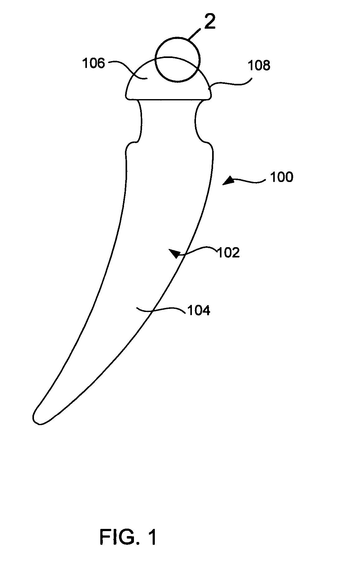
[0043]With reference to FIG. 1, a preferred embodiment of the present invention will be described in terms of a hip prosthesis (hip) 100 for implanting in the body of a patient. However, this is only by way of example, and it should be understood the present invention can practiced on many other medically implanted devices, including without limitation, knee, shoulder and elbow prostheses, as well as many other devices. Note FIG. 5, discussed below.

[0044]The hip prostheses 100 must be constructed completely of biocompatible materials in order to ensure acceptance of the prostheses by the patient's body. A biocompatible material is one that will not cause an adverse reaction with a host patient, and that will not co...


PUM

PropertyMeasurementUnit
thickaaaaaaaaaa
thickaaaaaaaaaa
thickaaaaaaaaaa

Abstract

A method of depositing a hard wear resistant surface onto a porous or non-porous base material of a medical implant. The medical implant device formed by a Laser Based Metal Deposition (LBMD) method. The porous material of the base promotes bone ingrowth allowing the implant to fuse strongly with the bone of a host patient. The hard wear resistant surface provides device longevity when applied to bearing surfaces such as artificial joint bearing surface or a dental implant bearing surface.

Description

CROSS-REFERENCE TO RELATED DOCUMENTS[0001]This patent application claims benefit of pending prior U.S. Provisional Patent Application Ser. No. 60 / 527,118, filed Dec. 3, 2003 by Daniel F. Justin et al. for LASER ENGINEERED NET SHAPING OF IMPLANT STRUCTURES, which patent application is hereby incorporated herein by reference.FIELD OF THE INVENTION[0002]The present invention relates to the formation of biocompatible materials onto a medical implant device, and more particularly to the use of laser based metal deposition of biocompatible materials onto a porous base material.BACKGROUND OF THE INVENTION[0003]The advancement of enhanced materials for the use of medical implants, such as joint prostheses have immensely improved the quality of life for many people over the past century. Devices such as artificial hips, knees, shoulders and other devices have allowed people who would otherwise have suffered from chronic pain and physical limitation to live active, comfortable lives. The deve...

Claims


Application Information

Patent Timeline
Patent Type & Authority Patents(United States)
IPC IPC(8): B32B15/01A61F2/02B32B15/16C23C14/14C23C14/22A61C8/00A61C13/00A61F2/00A61F2/30A61F2/36A61F2/38A61F2/40A61F2/42A61L27/04A61L27/30A61L27/56B23K26/34B32B3/10B32B5/14C23C4/02C23C4/12C23C4/18C23C24/10C23C26/00C23C26/02C23C28/00C23C28/02
CPCA61C8/0012A61F2/30767A61F2/36A61F2/3859A61F2/4225A61F2/4241A61L27/04A61L27/306A61L27/56C23C4/02C23C4/12C23C4/18C23C24/10C23C26/00C23C26/02C23C28/021C23C28/023C23C28/028Y10T428/12931A61F2002/30535A61F2250/0058B23K2203/14Y10T428/12806Y10T428/12847Y10T428/12812Y10T428/12826Y10T428/12493Y10T428/12458A61C13/0018B23K2103/14
Inventor JUSTIN, DANIEL F.STUCKER, BRENT E.
Owner MEDICINELODGE
Why Eureka
Try Eureka