
Zero step sill extruded flush threshold door seal system

a technology of flush threshold and extrusion, which is applied in the field of weather tight sealing, can solve the problems of inability to use, inconvenient use, and inability to meet the requirements of the user, and achieve the effect of facilitating the lowering of the flexible weather seal

Inactive Publication Date: 2011-12-13
JELD-WEN
View PDF12 Cites 35 Cited by
  • Summary
  • Abstract
  • Description
  • Claims
  • Application Information

AI Technical Summary

Benefits of technology

[0019]Another advantage of the flush threshold door seal system is to provide a flush surface entryway that will not present an impediment to the handicap including those in wheelchairs.
[0025]Another advantage of an alternate embodiment of the flush threshold door seal system is that it provides a flush surface entryway that will not present an impediment to the handicap including those in wheelchairs.

Problems solved by technology

Conventional thresholds of varying heights with weather strips are a problem for the elderly being a trip hazard when going through.
With large openings, the conventional thresholds with weather seals or doors with weather seals attached are not desirable and the need for a flush surface is necessary for wheelchair travel.
It would not be practical to be used as a means of sealing an exterior opening to a residence, office building or open-air mall and it would be a definite impediment to the operation of a wheelchair.
Although this type of sealing means will work over a flush floor surface, it is permanently attached to the lower surface of the doors and drags on the floor every time the doors are opened and closed.
It does not incorporate a desirable appearance for high-end homes, office buildings or open-air malls.
Although this patent addresses a door seal for use with bi-parting doors, either sliding or folding doors, it addresses the vertical surfaces and does not take into account the lower surface adjacent to the threshold area.
None of these previous efforts, however, provides the benefits attendant with the flush threshold door seal system.

Method used


Image

  • Zero step sill extruded flush threshold door seal system
  • Zero step sill extruded flush threshold door seal system
  • Zero step sill extruded flush threshold door seal system

Examples


Embodiment Construction

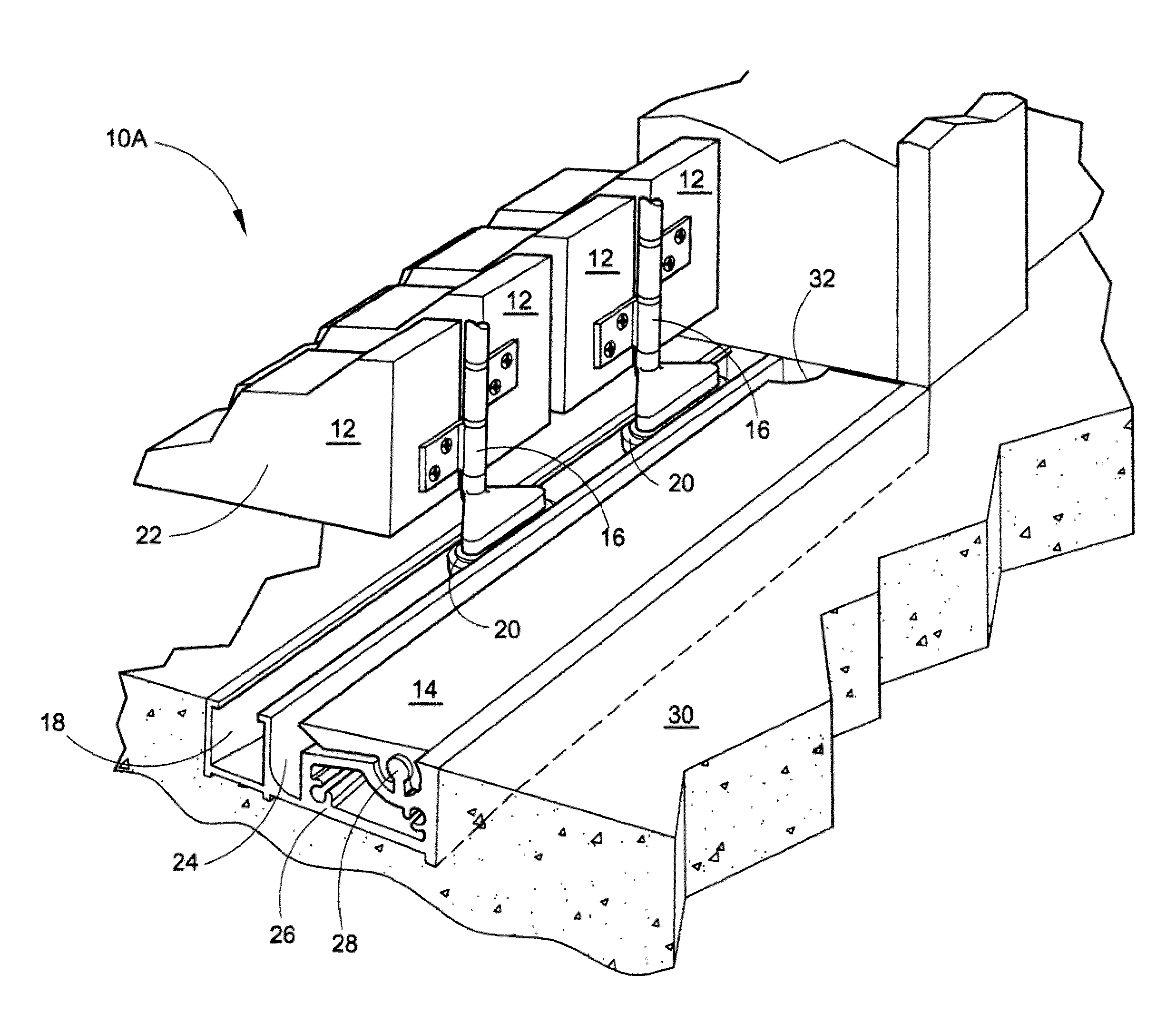
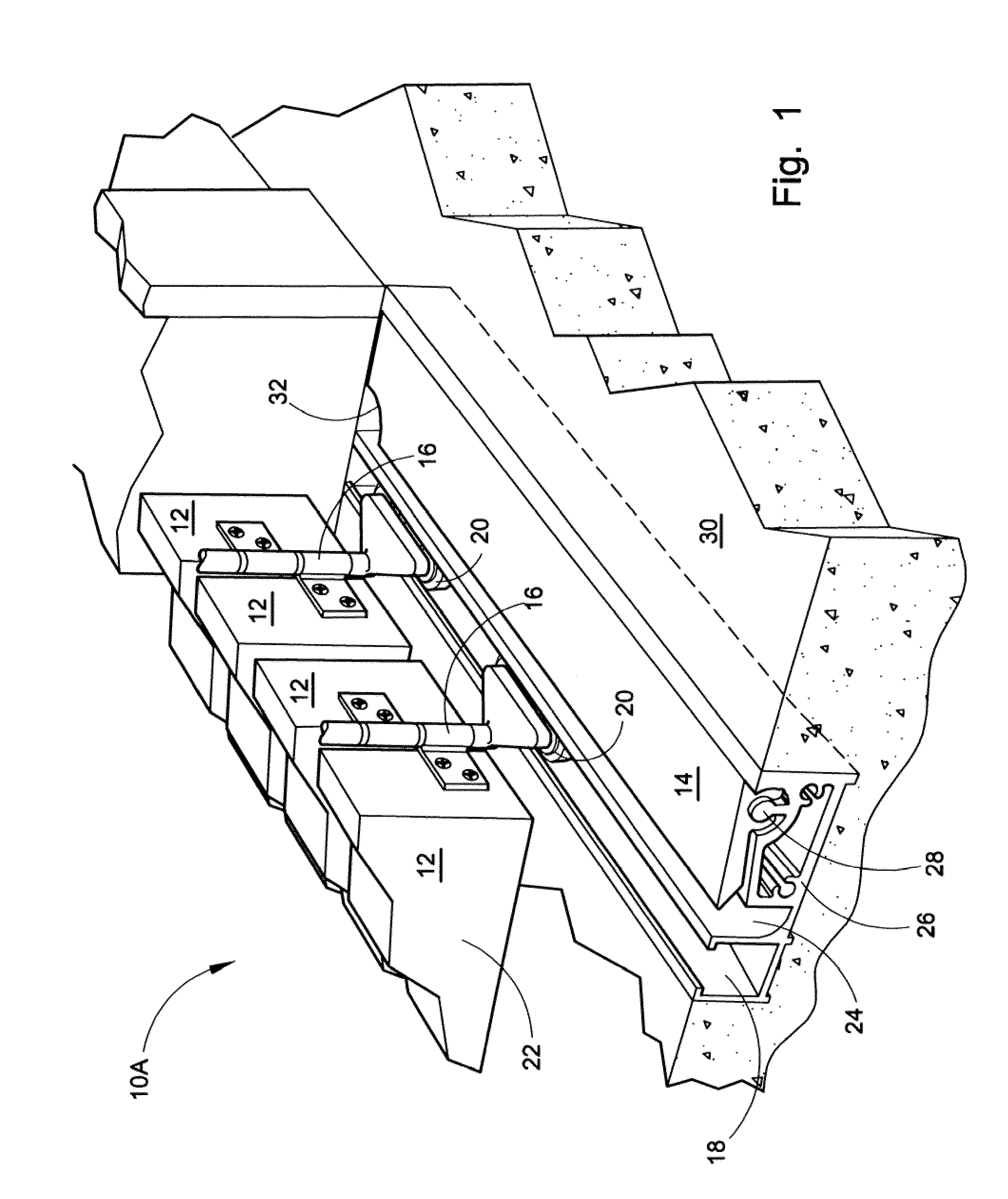
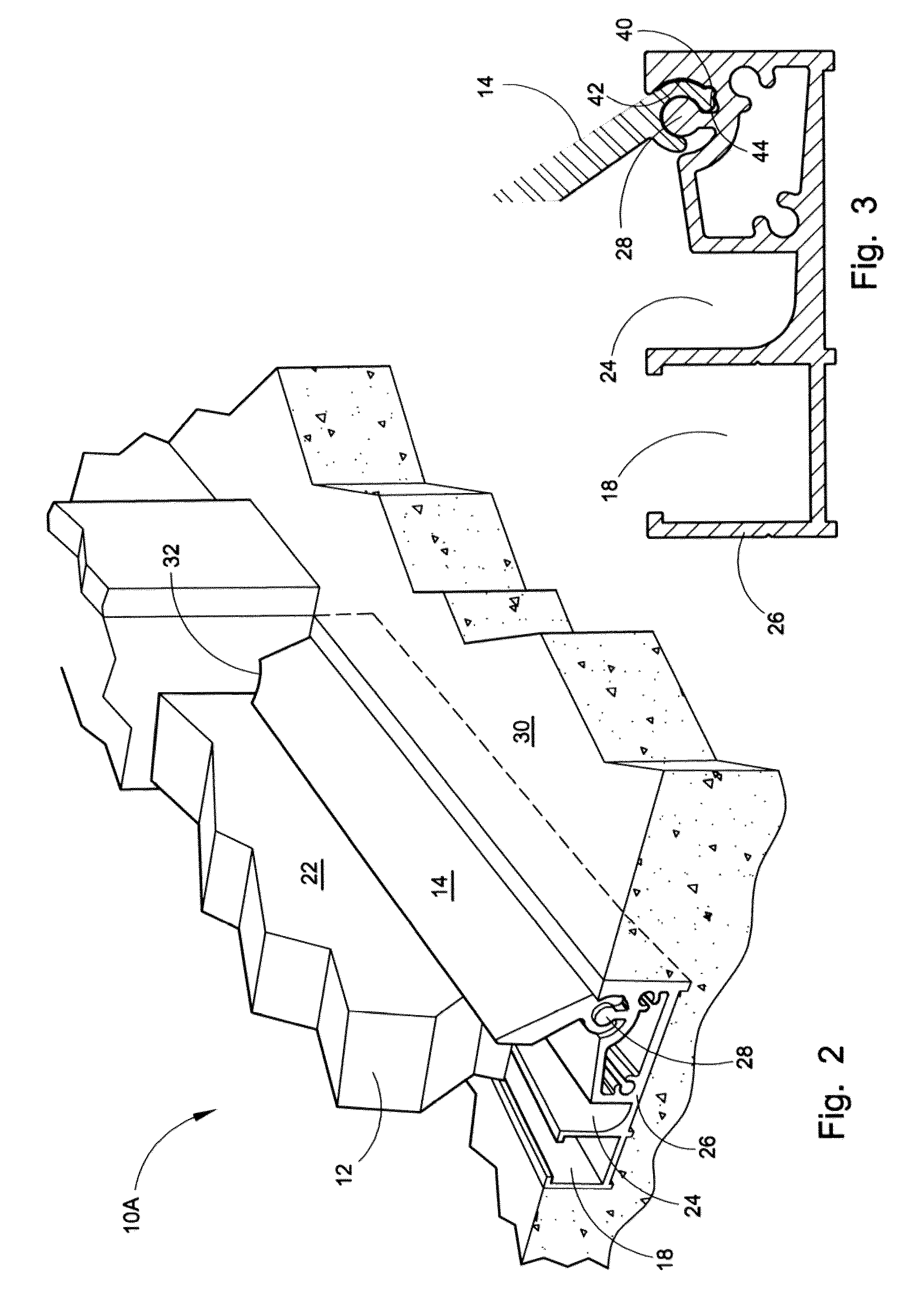
[0044]Referring now to the drawings, wherein similar parts of the flush threshold door seal system in the manual mode 10A and flush threshold door seal system in the automatic mode 10B along with the alternate embodiment of the flush threshold door seal system 10C are identified by like reference numerals. There is seen in FIG. 1 a perspective view of the flush threshold door seal system 10A with the folding doors 12 fully open and the flexible weather seal 14 in the retracted or down position. With this type of folding door 12, a unique door hinge 16 is used where the folding doors 12 are offset from the roller guide track 18 in which the rollers 20 translate when the folding doors 12 are opened and closed. With this offset of the hinge 16, the door faces 22 of the folding doors 12 rotate against the flexible weather seal 14. A secondary transverse door-locking cavity 24 is adjacent to the roller guide track 18 furnishing a locking means when the folding doors 12 are in the closed ...


PUM


Abstract

The present application is directed to a manual or automatic flush threshold door seal system used on folding exterior doors along with an alternate embodiment for conventional exterior entryway doors that will not impede the passage of a wheelchair. A flexible weather seal can be put in a retracted or down position within an aluminum extrusion imbedded within the threshold providing a flush access surface and may be raised up into the upright position providing an adequate weather seal.

Description

FIELD OF THE INVENTION[0001]This application applies to the weather tight sealing of a door threshold by providing a flush threshold lower door seal that will not impede the passage of a wheelchair.BACKGROUND OF THE INVENTION[0002]The thresholds on doors along with the added height of an adequate weather seal have long been an impediment to the movement of wheelchairs through doorways. There is a growing need for adequately weather sealing of doorways while providing a flush surface to walk through or operate a wheel chair. Conventional thresholds of varying heights with weather strips are a problem for the elderly being a trip hazard when going through. Additionally the weather sealing of doorways is only necessary during inclement weather and the rest of the time the passage of cool air under the door can be a benefit. This unique flush threshold door seal system provides a new and unique sealing method for a wide variety of doorways.[0003]The initial purpose of the design is to p...

Claims


Application Information

Patent Timeline
Patent Type & Authority Patents(United States)
IPC IPC(8): E05D15/26E06B7/16E06B1/70
CPCE05D15/0656E06B1/70E06B3/4636E05Y2201/11E05Y2600/322Y10S277/921E05Y2900/132
Inventor JONES, TOBYPOWER, MATTHEW W.
Owner JELD-WEN
Learn More