Multi-axial transverse rod connector

a multi-axial, transverse rod technology, applied in the field of surgery, can solve the problem of not being able to rotate the components of the multi-axial rod connector using the lateral translation mechanism

Active Publication Date: 2011-12-13
ALPHATEC SPINE INC
View PDF7 Cites 56 Cited by
  • Summary
  • Abstract
  • Description
  • Claims
  • Application Information

AI Technical Summary

Benefits of technology

[0019]Some embodiments of the present invention relate to a device that connects two lateral rods together to increase torsional rigidity of the device. The variability in the device allows it to attach two rods that are not parallel or may / should not be parallel to each other, such as, rods that are diverging or converging.
[0021]Some embodiments of the present invention may include a multi-axial rod connector that is variable and that may include a multi-axial ball and socket joint. Additionally, the device may include a lateral translation mechanism. The multi-axial ball and socket joint may allow unlimited rotational freedom and limited angulation of the device. The lateral translation mechanism may include of a rod, a receiving member, a locking connector, and a locking connector setscrew. The lateral translation mechanism may be used for lateral translation of the components of the multi-axial rod connector. In some embodiments, it may not be possible to rotate components of the multi-axial rod connector using the lateral translation mechanism. Other embodiments may permit rotational movement of certain components.
[0024]The locking capabilities of the device in the present invention provide a number of advantages. The poly-axial locking mechanism may employ a wedging effect along with a cooperation from the bushing structure to lock the device into a static position. The bushing may also act as a compression device that creates friction on the ball portion of the poly-axial rod. This may allow the device to be more stable (rather than free-moving) during insertion of the spinal rods into the multi-axial rod connector.
[0025]In yet another embodiment, the lateral translation mechanism can use a separate locking connector to lock the lateral translation of the device. This component may be held in place by mating a “boss” on the bottom of the static link with a “hole” in the bottom of the locking connector. The open channel in the static link allows for manufacturability of the curved channel.

Problems solved by technology

In some embodiments, it may not be possible to rotate components of the multi-axial rod connector using the lateral translation mechanism.

Method used


Image

  • Multi-axial transverse rod connector
  • Multi-axial transverse rod connector
  • Multi-axial transverse rod connector

Examples


Embodiment Construction

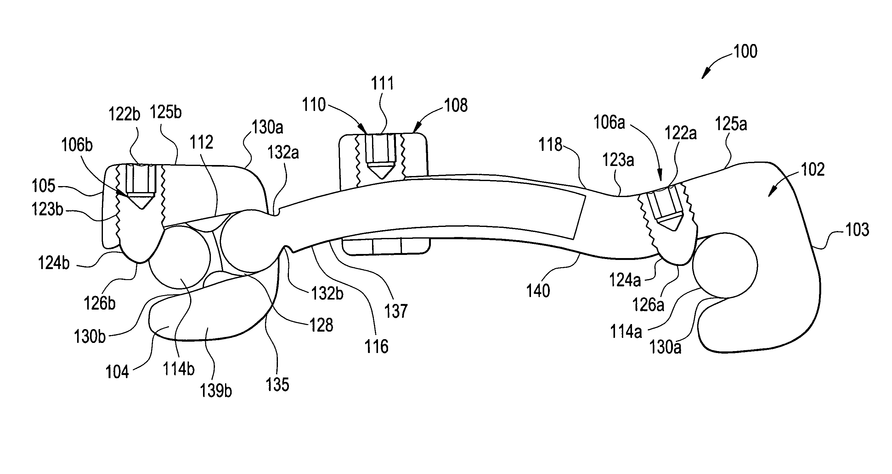
[0039]In some embodiments, the present invention relates to a transverse rod connector that is configured to connect and maintain a spaced-apart relationship between bone alignment rods.

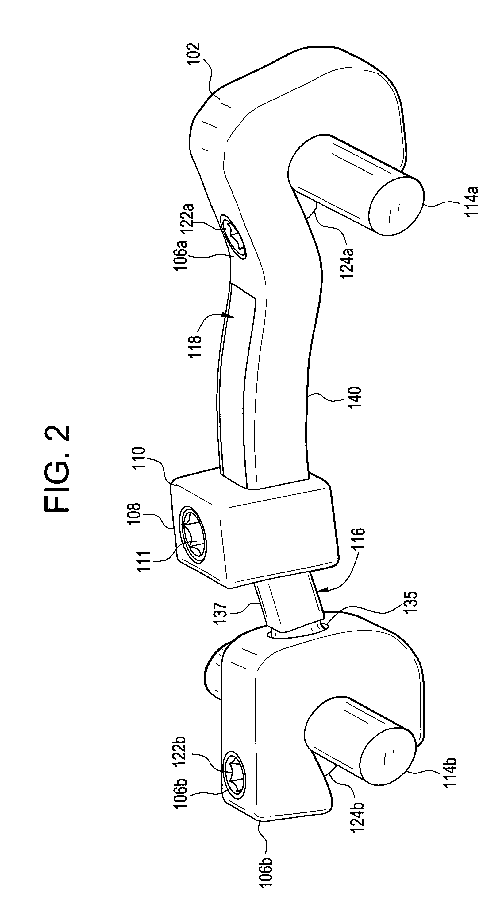
[0040]FIGS. 1-9 illustrate an exemplary multi-axial transverse rod connector 100, according to some embodiments of the present invention. The connector 100 includes a fixed hook 102, a variable hook 104, rod locking setscrews 106 (a, b), a multi-axial or poly-axial connector rod 116, and a locking connector 108 having a locking connector setscrew 110. The hooks 104 and 102 are configured to accommodate placement and securing of connector rods 114a and 114b. Connector rods 114 can be spinal connector rods or any other rods used in surgical procedures. The rods 114 can be secured at any angles and / or axial planes with regard to each other (e.g., rods can be converging, diverging, parallel, perpendicular to each other, etc.).

[0041]The fixed hook 104 further includes a housing 103 having a poly-axial rod...


PUM


Abstract

A multi-axial rod connector for connecting spinal rods is provided. The rod connector includes a poly-axial rod assembly configured to include a lateral translation mechanism and a fixed hook configured to be rigidly coupled to one end of the poly-axial rod assembly. The fixed hook includes a fixed hook cavity configured to secure a spinal rod. The rod connector also includes a variable hook configured to be rotatably coupled another end of the poly-axial rod. The variable hook includes a variable hook cavity configured to secure another spinal rod. The lateral translation mechanism is configured to change distance between the fixed hook and the variable hook.

Description

CROSS-REFERENCE TO RELATED APPLICATIONS[0001]The present application claims priority to U.S. Provisional Patent Application No. 60 / 849,871 to Purcell, filed Oct. 6, 2006, entitled “Multiaxial Transverse Rod Connector”, and incorporates its disclosure herein by reference in its entirety.[0002]The present application relates to U.S. patent application Ser. No. 11 / 544,893, to Laurence et al., filed Oct. 6, 2006, entitled “Transverse Rod Connector”, which claims priority to U.S. Provisional Application No. 60 / 725,031, to Laurence et al., filed Oct. 7, 2005, and titled “Transverse Rod Connector”, and incorporates entire disclosures of these applications herein by reference.BACKGROUND OF THE INVENTION[0003]1. Field of the Invention[0004]The present invention relates generally to the field of surgery, and more specifically, to connector devices for connecting and maintaining a spaced apart relationship between bone alignment rods (“transverse rod connectors”).[0005]2. Background of the Inv...

Claims


Application Information

Patent Timeline
Patent Type & Authority Patents(United States)
IPC IPC(8): A61B17/70
CPCA61B17/7052
Inventor PURCELL, THOMAS
Owner ALPHATEC SPINE INC
Why Eureka
Try Eureka