Sewing machine

a sewing machine and latching element technology, applied in the field of sewing machines, can solve the problems of increasing the solenoid, increasing the cost, and reducing the disengagement speed of the latching element from the engaging member of the needle bar

Inactive Publication Date: 2011-12-20
BARUDAN KK
View PDF11 Cites 0 Cited by
  • Summary
  • Abstract
  • Description
  • Claims
  • Application Information

AI Technical Summary

Benefits of technology

[0025]An object of the present invention is to provide a sewing machine that naturally enables performing normal sewing work, and that enables skipping a stitch during the sewing work.
[0026]Another object is to provide a sewing machine that enables causing a latching portion and an engaging device of the needle bar to be accurately engaged and disengaged when skipping the stitch during the sewing work.

Problems solved by technology

Employing a larger solenoid leads, however, to an increase in cost and is hence not advantageous.
However, increasing the spring force of the spring inside the solenoid inversely creates resistance against the driving force of the solenoid driving the latching element to be disengaged from the engaging member of the needle bar, thus decreasing the disengaging speed of the latching element from the engaging member of the needle bar.
Increasing the biasing force creates, however, greater force resisting against the driving force of the solenoid causing the latching element to be disengaged from the engaging member of the needle bar, thus leading to the disadvantage that the latching element gets disengaged from the engaging member of the needle bar at reduced speed.
Consequently, as described above, the conventional sewing machine according to the patented document 1 has the drawback that the increase in vertically reciprocating speed of the needle bar cannot be achieved, because it is impossible to increase the engaging speed nor the disengaging speed between the latching element and the engaging member of the needle bar according to the increase in vertically reciprocating speed of the needle bar.
Thus, the needle bar repeats the descending and ascending motions in the vicinity of the upper dead point, which creates the drawback that the position of the needle bar is not stabilized immediately upon reaching the upper dead point.
Since the needle bar repeats the vertical reciprocating motion even after reaching the upper dead point, and is hence not stably set at the position corresponding to the upper dead point, the lock element of the carriage cannot be accurately engaged with the engaging member of the needle bar even though the carriage ascends again after descending to thereby have the lock element get engaged with the engaging member of the needle bar at the position corresponding to the upper dead point, because the timing is too short before the needle bar starts to descend after reaching the upper dead point, and therefore only the carriage descends without being accompanied with the needle bar, which leads to failure in performing the sewing work as designed, and to create a defective embroidery pattern.

Method used


Image

  • Sewing machine
  • Sewing machine
  • Sewing machine

Examples


Embodiment Construction

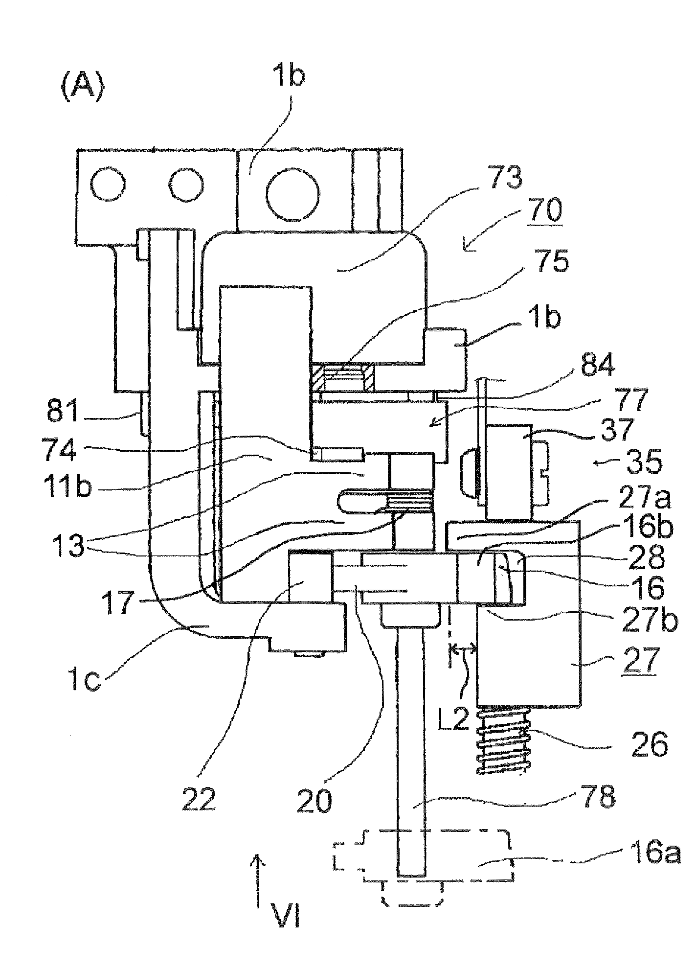
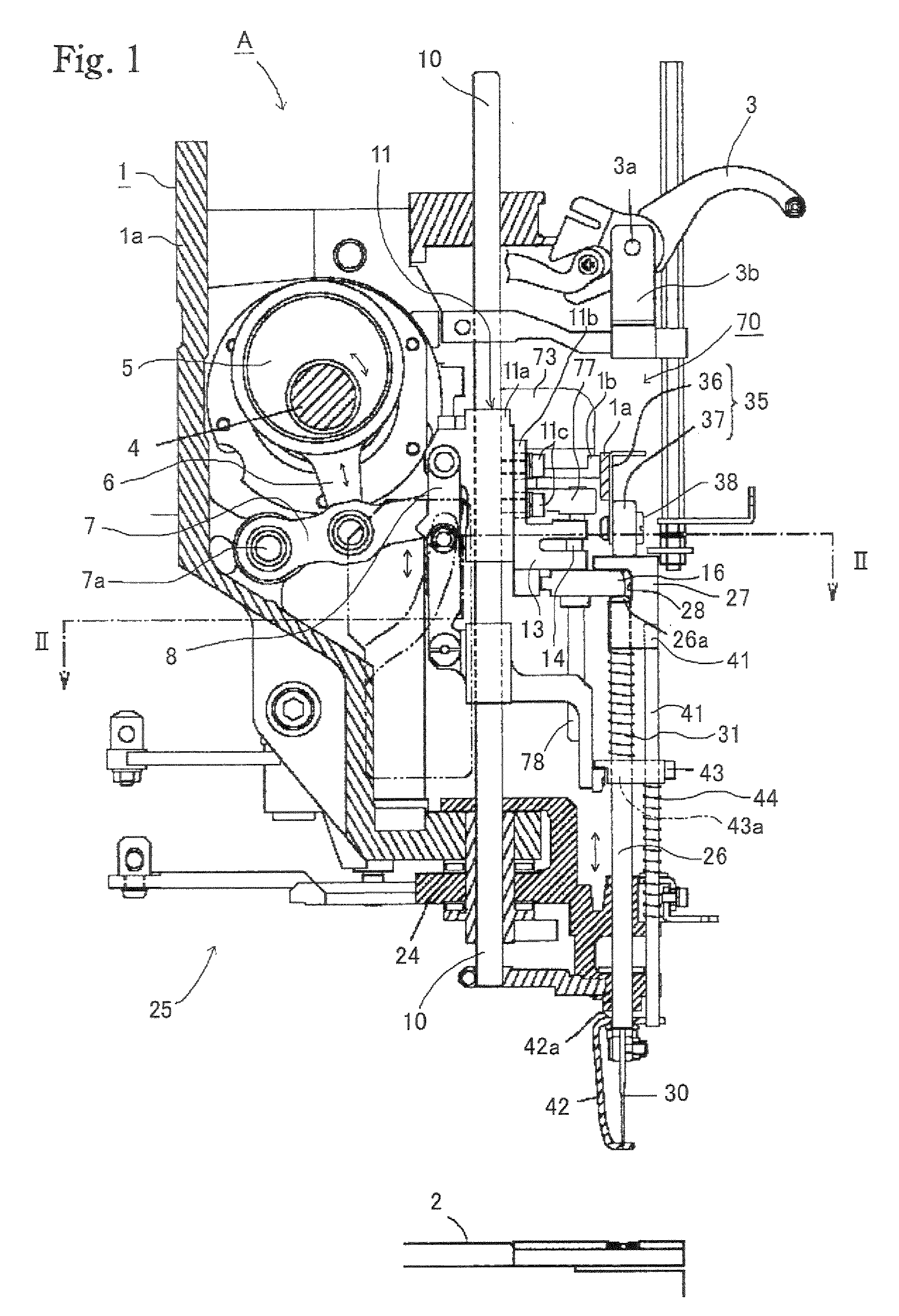
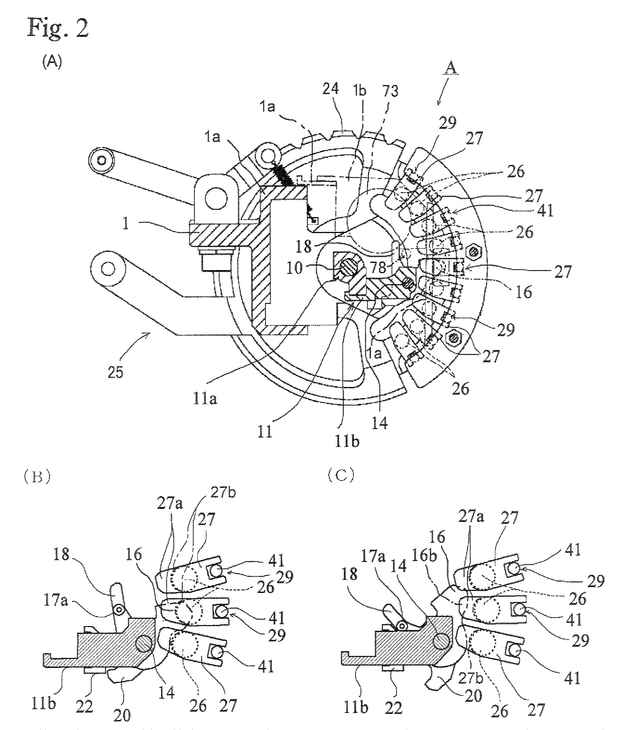
[0051]Hereunder, an embodiment of the present invention will be described referring to the drawings. In FIGS. 1 and 2A to 2C, the structure involving a frame 1, a thread take-up 3, components 24 to 31 associated with a needle bar, components 35 to 38 associated with a needle bar stopper, components 41 to 44 associated with a presser foot, components 5 to 22 associated with a carriage, components associated with a skipping mechanism 70 (except those related to the description of novel technical matters (such as structure, combination or function of the components) introduced in the following description given regarding such components as a engaging device 27 of the needle bar, a second latching portion 16b of the carriage, and an operating member 78) represents a structure made up so as to attain similar movement and function to those of a sewing machine constituted of the components of a conventionally known model, for example the sewing machine shown in FIG. 1 of the patented docum...


PUM


Abstract

An object of the present invention is to provide a sewing machine that naturally enables performing normal sewing work, and that enables skipping a stitch during the sewing work, and furthermore, another object is to provide a sewing machine that enables causing a latching portion and an engaging device of the needle bar to be accurately engaged and disengaged when skipping the stitch during the sewing work.An operating member return spring is provided between the operating member and the frame; and the operating member return spring is formed such that, in a process that upon supplying power to the solenoid the latching portion is being driven from the engaging position to the retreated position, a spring force of the operating member return spring is not, or only weakly exerted on the operating member while the latching portion is located between the engaging position and the vicinity of a departing point where the latching portion starts to be disengaged, and that the spring force is relatively strongly exerted on the operating member while the latching portion is located between the vicinity of the departing point and the retreated position, so that resilient force is stored in the operating member return spring with the movement of the operating member.

Description

FIELD OF THE INVENTION[0001]The present invention relates to a sewing machine, and more particularly to a sewing machine that enables skipping a stitch during the sewing work.BACKGROUND OF THE INVENTION[0002]Conventionally, sewing machines that enable skipping a stitch during the sewing work have been widely known. An example of those sewing machines can be found in the patented document 1. The sewing machine according to the patented document 1 has the following structure.[0003]The sewing machine includes a needle bar, having an engaging member (engaging device) provided at an upper portion thereof and disposed so as to vertically reciprocate with respect to a head frame; and a carriage set to be driven by a main shaft and to vertically reciprocate parallel to the needle bar; and the carriage is provided with a latching element (latching portion) which is set to move between an engaging position where the latching element can be engaged with the engaging member and a retreated posi...

Claims


Application Information

Patent Timeline
Patent Type & Authority Patents(United States)
IPC IPC(8): D05B69/00
CPCD05B69/10D05B19/14D05B55/10D05B55/14D05C11/06
Inventor KASUGAI, KEISUKE
Owner BARUDAN KK
Why Eureka
Try Eureka