Operational mechanism for movable body

a technology of movable bodies and mechanism bodies, which is applied in the direction of scaffolds, machines/engines, and girders, etc., can solve problems such as obstacles such as the hook

Active Publication Date: 2011-12-20
NIFCO INC
View PDF33 Cites 28 Cited by
  • Summary
  • Abstract
  • Description
  • Claims
  • Application Information

AI Technical Summary

Problems solved by technology

However, the hook may be an obstacle when it is not being used, since it projects towards a vehicle inner side.

Method used


Image

  • Operational mechanism for movable body
  • Operational mechanism for movable body
  • Operational mechanism for movable body

Examples


first embodiment

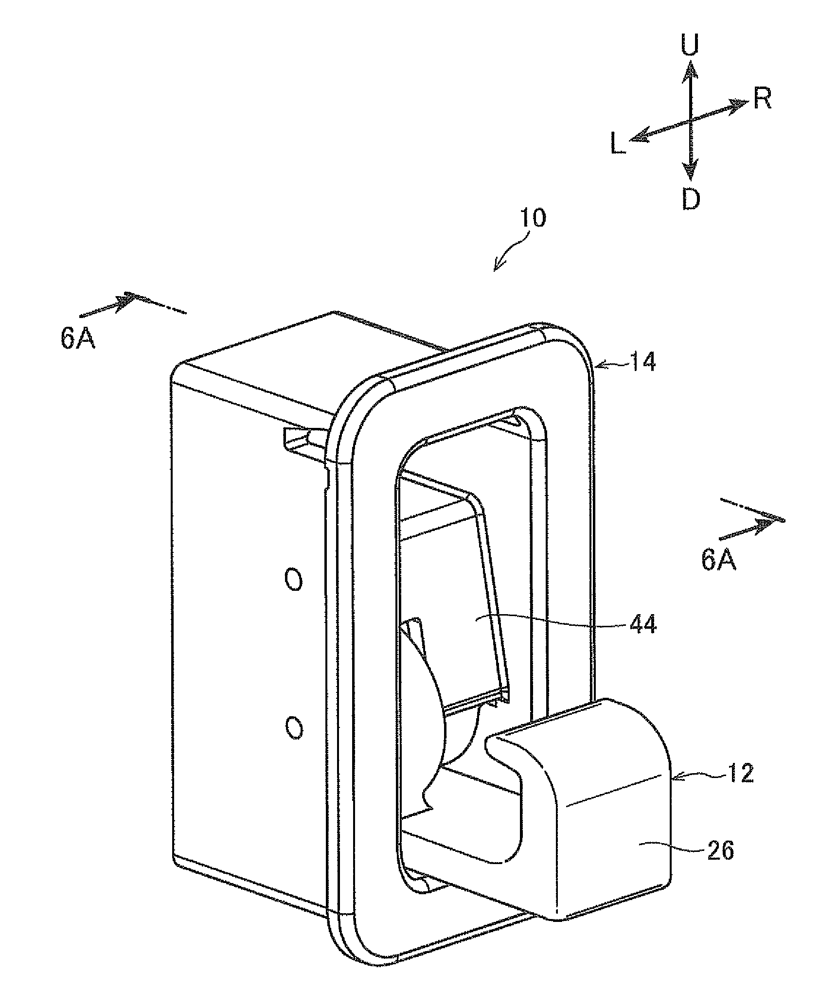
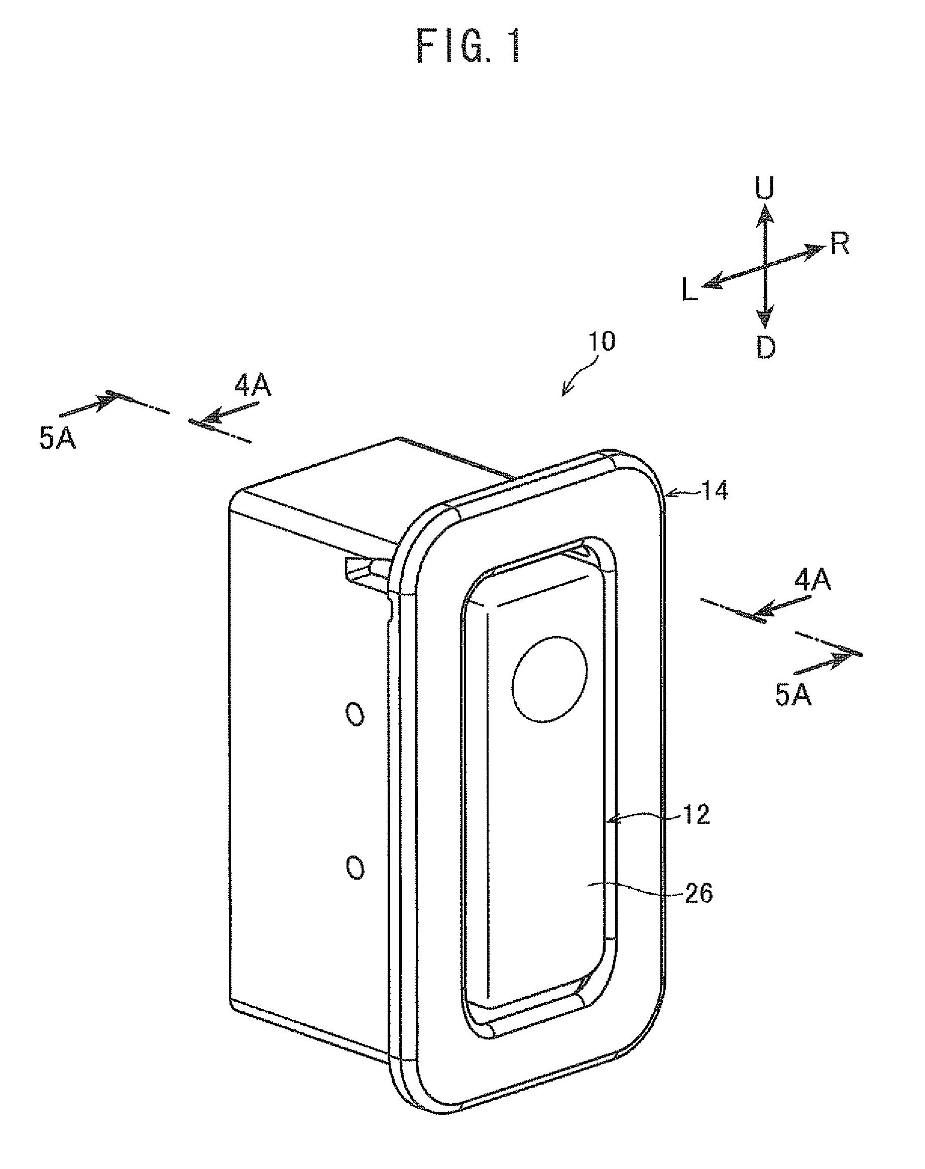
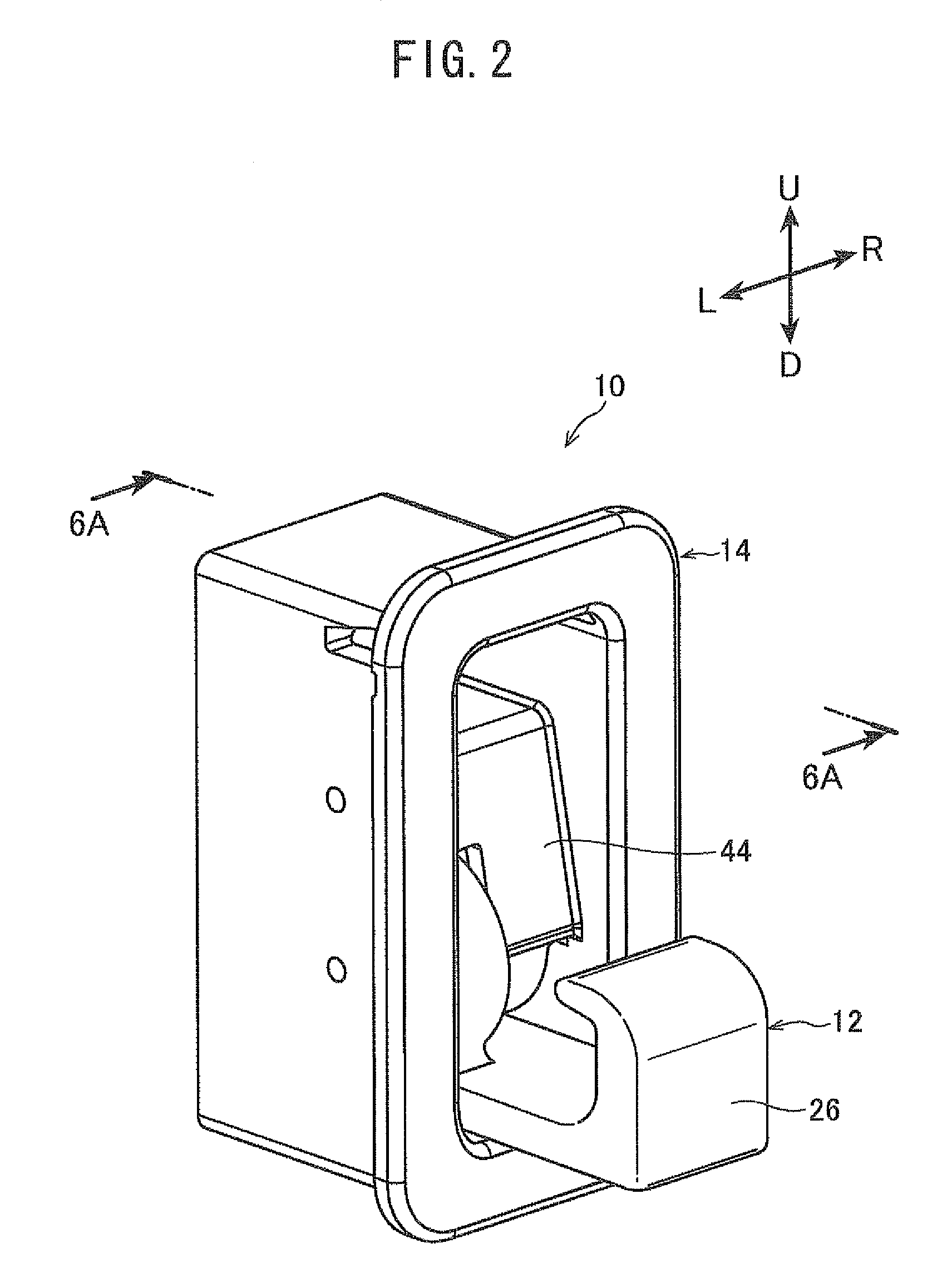
[0027]In the first embodiment, a hook device 10 shown in FIGS. 1-3 is provided at a vehicle body panel or the like, and a hook member (movable body) 12 thereof faces an interior space and may be opened and closed. For ease of explanation, the orientation of hook device 10 in FIGS. 1-3 is made a reference orientation, and up, down, left and right directions (indicated as U, D, L and R, respectively) are as shown in these figures.

[0028]Hook device 10 is provided with a box shaped case (support body) 14, which may house hook member 12 therein. A flange portion 16 extends from an end surface of a side wall of the case 14 towards an outer side, around the entire periphery of the case 14. Upper and lower axial support holes 18 and 20 are provided at the side wall in a length direction of the case 14, and shafts 22 and 24 are respectively fixed in the axial support holes 18 and 20.

[0029]Hook member 12 includes a hook portion 26, a leading end side of which bends in a hook shape, and a subs...

second embodiment

[0082]A second embodiment is shown in FIG. 7. In the first embodiment, gear members 40 and 54 are used to interlock with the operation of hook member 12. In the present embodiment, in a hook device 79, a rotating member 80 is used to interlock with the operation of hook member 12. Further, parts identical to those of the first embodiment are labeled with the same reference numerals, and detailed descriptions thereof are omitted.

[0083]FIGS. 8A-8C are sectional views of rotating member 80 corresponding to the lines of section shown in FIG. 7. As shown in FIG. 7, rotating member 80 is provided with an axial portion 82, which contacts with a projecting portion 88 provided at an upper portion of drum 86 of hook member 84.

[0084]If, when hook member 84 is in a closed position as shown in FIG. 9A, hook member 84 is pushed in a pushing-in direction, axial portion 82 is pushed via projecting portion 88, as shown in FIG. 9B. As a result, as shown in FIGS. 10A and 10B, rotating member 80 rotate...

third embodiment

[0087]A third embodiment is shown in FIG. 13. Parts identical to those of the first embodiment are labeled with the same reference numerals, and detailed descriptions thereof are omitted.

[0088]As shown in FIGS. 14 and 15, in the present embodiment, a hook member 101 moves upward and downward (vertically) in a hook device 100. Hook member 101 includes hook portion 26 and a rack portion 102. Rack potion 102 is provided at an inner surface of hook member 101, and positioned at a side opposite to hook portion 26. Pinion portions 106 formed at an outer peripheral surface of a cylindrical rotating body 104 are configured to engage with rack portion 102.

[0089]Rotating body 104 is axially supported by shaft 24 and may rotate around shaft 24. As a result of the rotation of rotating body 104, rack portion 102 moves vertically via pinion portions 106, and hook member 101 moves vertically via rack portion 102. An attachment portion 108 is provided at rotating body 104, and one end of reversing ...


PUM


Abstract

The invention provides an operational mechanism for a movable body in which, after a movable body is in an opened state, the movable body can return to a closed position, including a movable body rotatably attached to a support and rotatable between an engaged position, a closed position, and an open position; a rotating member rotatably attached to the support, that rotates due to movement of the movable body to the engaged position; a biasing member, one end of which is attached to the movable body, and the other end of which is attached to the rotating member; and an operation member, which rotates the rotating member, changes the biasing position of the biasing member with respect to the center of rotation of the movable body, and generates in the biasing member a rotational force that moves the movable body to the closed position or the open position.

Description

CROSS-REFERENCE TO RELATED APPLICATION[0001]This application claims priority under 35 USC 119 from Japanese Patent Application No. 2008-253324, the disclosure of which is incorporated by reference herein.BACKGROUND[0002]1. Technical Field[0003]The present invention relates to an operational mechanism for a movable body which may be opened and closed, such as a hook or the like.[0004]2. Related Art[0005]In a vehicle inner space, a claw shaped (substantially “L” shaped) hook is provided projecting towards a vehicle inner side and is used to support clothing, bags, and the like. However, the hook may be an obstacle when it is not being used, since it projects towards a vehicle inner side.[0006]To address the above, in Japanese Patent Application Laid-Open (JP-A) No. 2006-35994, a hook and a case storing the hook are linked by a biasing means, and the hook is biased in a storage direction towards the case. When the hook is used, a finger or the like is used to apply resistance to a bias...

Claims


Application Information

Patent Timeline
Patent Type & Authority Patents(United States)
IPC IPC(8): F03G1/00B60R7/10F16B45/00F16H31/00A41D27/22E04G3/00
CPCB60R7/10Y10T74/1552Y10T24/48
Inventor NEMOTO, TAKEHIKO
Owner NIFCO INC
Why Eureka
Try Eureka