Air blower apparatus having blades with outer peripheral bends

a technology of air blower and blade, which is applied in the direction of other chemical processes, heating types, vessel construction, etc., can solve the problems of high noise during operation, inconvenience of outdoor unit construction, and failure of noise reduction methods alone, so as to reduce the noise generated by the air blower apparatus (4) itself, reduce the weight and cost of the blade, and enhance the effect of noise reduction

Inactive Publication Date: 2006-02-07
DAIKIN IND LTD
View PDF13 Cites 42 Cited by
  • Summary
  • Abstract
  • Description
  • Claims
  • Application Information

AI Technical Summary

Benefits of technology

[0058]Accordingly, the air blower apparatus (4) of the present invention provides the following beneficial effects.
[0059](i) Noise generated by the air blower apparatus (4) itself is reduced, and noise when the air blower apparatus (4) is incorporated within an air conditioning apparatus outdoor unit is reduced effectively.
[0060](ii) Even in the case where the length of chord of the blade (13, 13, 13) is shortened for accomplishing reduction in weight and costs of the blade (13, 13, 13), the blade tip vortex (β) will not depart from the suction surface, and will not interfere with the adjoining blade. This provides enhanced noise reduction effects, and suppresses the drop in air supplying performance.
[0060](ii) Even in the case where the length of chord of the blade (13, 13, 13) is shortened for accomplishing reduction in weight and costs of the blade (13, 13, 13), the blade tip vortex (β) will not depart from the suction surface, and will not interfere with the adjoining blade. This provides enhanced noise reduction effects, and suppresses the drop in air supplying performance.
[0062](iv) Additionally, since the bent part achieves a rib action, this increases the rigidity of the blade (13, 13, 13). As a result, the blade (13, 13, 13) can be thinned, thereby making it possible to further reduce the manufacturing costs of the blade (13, 13, 13). At the same time, the resistance to vibration of the blade (13, 13, 13) is improved, thereby reducing the generation of abnormal noise due to vibrations.

Problems solved by technology

Such an outdoor unit construction may produce inconvenience, i.e., high levels of noise during operation because of the noise generated by the propeller fan (4) itself and, in addition, because of the noise generated upon collision of an air flow discharged from the propeller fan (4) against a downstream structural member such as a fan guard (6) et cetera.
Unfortunately, these noise-reduction methods alone fail to provide solutions to the following problems.
This increases levels of noise to a further extent.
Accordingly, when incorporated within the air conditioning apparatus outdoor unit, discharge vortexes from between adjoining blades will interfere with the grilled structural member, thereby generating noise.

Method used


Image

  • Air blower apparatus having blades with outer peripheral bends
  • Air blower apparatus having blades with outer peripheral bends
  • Air blower apparatus having blades with outer peripheral bends

Examples


first embodiment

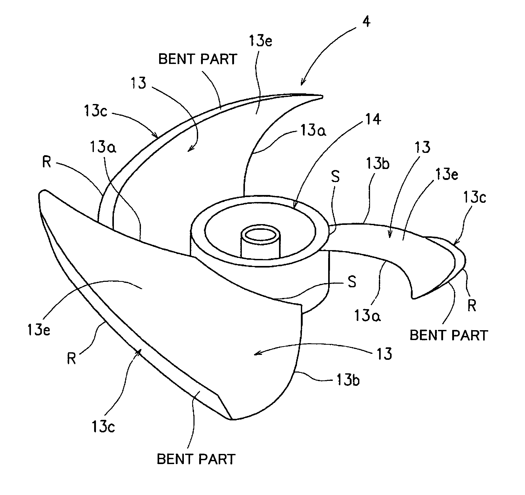
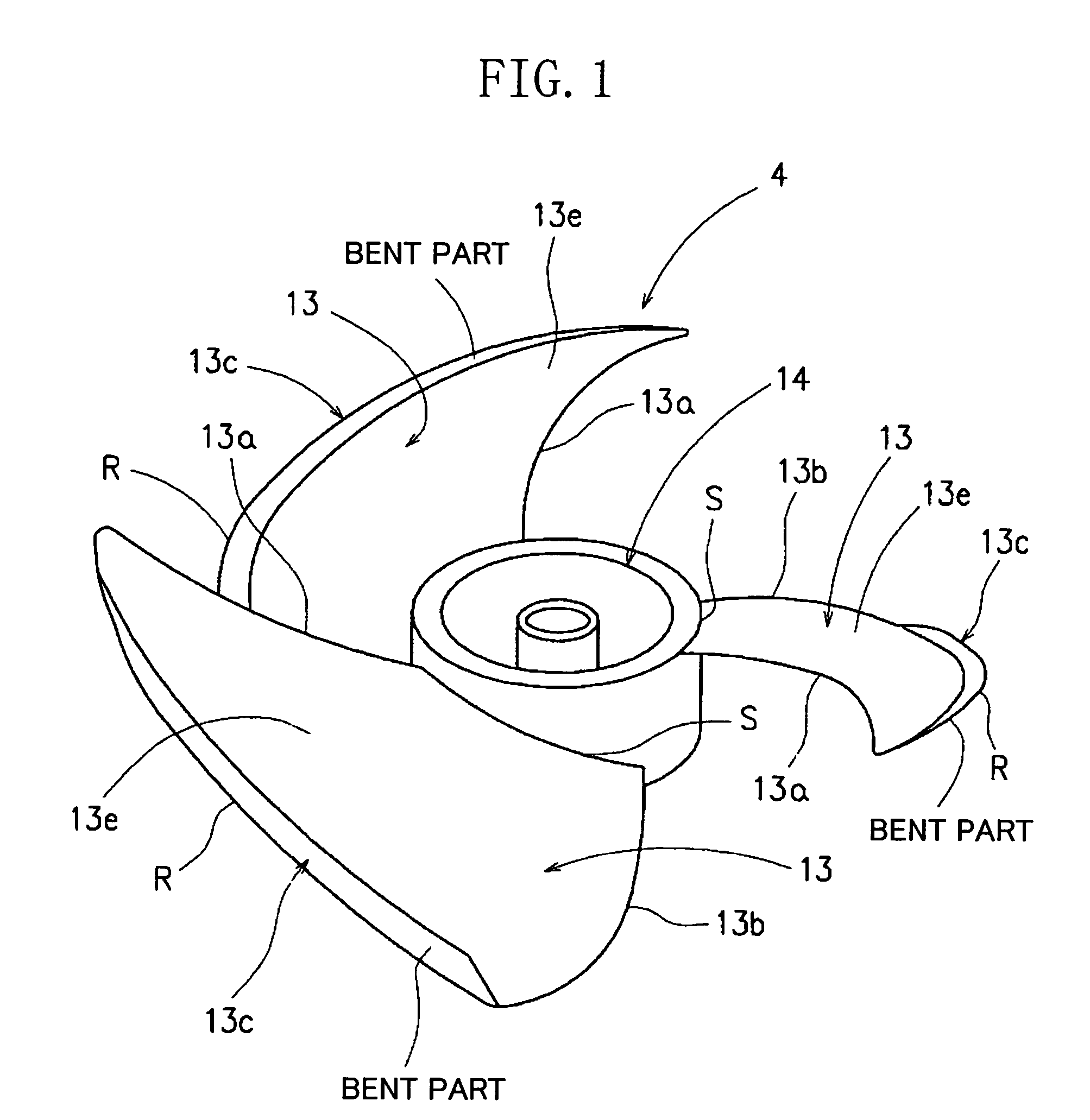
[0091]FIGS. 1–15 show structures and actions of an air blower apparatus (4) according to a first embodiment of the present invention. The air blower apparatus (4) is a propeller fan that is suitable for use in air conditioning apparatus outdoor units.

[0092]More specifically, FIGS. 1–11 illustrate basic structures and actions of an impeller section of the air blower apparatus (4), and FIGS. 12–15 illustrate shapes of a blade (13) of the impeller section according to several modification examples of the first embodiment.

Basic Structure of Impeller Section

[0093]Referring to FIGS. 1–11, the air blower apparatus (4), which is a propeller fan, has a hub (14) of synthetic resin. The hub (14) is a center of rotation of the air blower apparatus (14), and three identical blades (13, 13, 13) are disposed integrally along an outer peripheral surface of the hub (14).

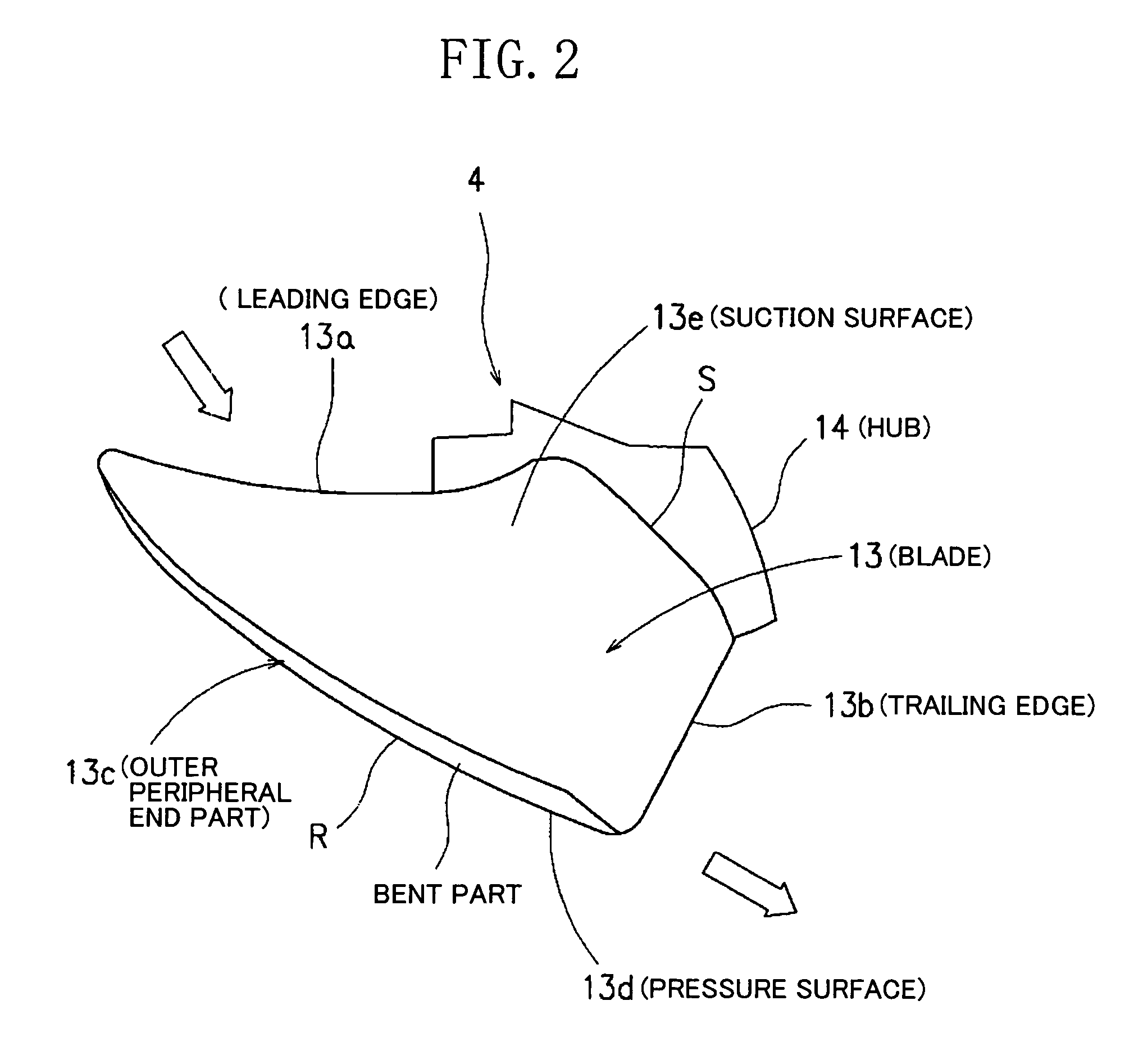
[0094]The blade (13, 13, 13) has a leading edge (13a) and a trailing edge (13b), wherein both an outer peripheral end (R) of the le...

first modification example

[0129]The shape of the bent part of the outer peripheral part (13c) of the blade (13, 13, 13) is not limited to the above-described linear shape. For example, as shown in FIGS. 12 and 13, the shape of the bent part may be a curved surface formed by curling partially the vicinity of a leading end of the bent part which is approximately linearly formed, i.e., only the vicinity of the outer peripheral end (R), toward the suction side. This enables an air flow to readily enter from the side of the pressure surface (13d) around into the suction surface (13e), thereby reducing the diameter of the blade tip vortex (β) to a further extent.

second modification example

[0130]For example, as shown in FIGS. 14 and 15, the bent part of the blade outer peripheral part (13c) may be approximately S-shaped. More specifically, in this second modification example, the entire shape of the bent part is formed into approximately an S-shape in the following way. A portion positioned ahead of a part (a) bent linearly toward the suction side is rebent toward the side of the pressure surface (13d) to form a blade extension surface (b) and its outer peripheral end (c) is bent toward the suction side, so that the bent part is S-shaped. Also for the case of such a configuration, the blade tip vortex (β) is reduced with effect and, in addition, it is possible to eliminate discharge vortexes from between adjoining blades.

Effects of First Embodiment

[0131]Accordingly, the air blower apparatus (4) of the first embodiment provides the following beneficial effects.

[0132](i) Noise generated by the air blower apparatus (4) itself is reduced, and, in addition, noise when the ...


PUM


Abstract

An air blower apparatus is provided including a hub which is a center of rotation, and a plurality of blades disposed along an outer peripheral surface of the hub and having leading and trailing edges and where both an outer peripheral end of the leading edge and an outer peripheral end of the trailing edge lie ahead relative to the rotative direction. An outer peripheral part of the blade may be bent toward the suction side in such a way as to form a starting point at which an airflow starts leaking, and the radial-direction width, W, of the bent part gradually increases from the vicinity of the leading edge to the vicinity of the trailing edge. A blade tip vortex (β) generated from a blade positioned ahead relative to the rotational direction F and a separation vortex from a pressure surface of a blade positioned behind relative to the rotational direction F offset each other, so that discharge vortexes are suppressed.

Description

[0001]This application is the national phase under 35 U.S.C. §371 of PCT International Application No. PCT / JP03 / 01825 which has an International filing date of Feb. 19, 2003, which designated the United States of America.TECHNICAL FIELD[0002]The present invention relates to the structure of an air blower apparatus such as a propeller fan and the like.BACKGROUND ART[0003]Axial blower apparatus, such as propeller fans and the like, generally find application as air blower apparatus for use in air conditioning apparatus outdoor units. Referring to FIGS. 16–18, there is shown a structure of an air conditioning apparatus outdoor unit which employs such an air blower apparatus.[0004]As shown in each of the figures, the aforementioned air conditioning apparatus outdoor unit comprises a main body casing (1) in which an air blower apparatus unit (3) is disposed on the air flow downstream side of a heat exchanger (2) on the side of a rear air inlet (10a). This air blower apparatus unit (3) is...

Claims


Application Information

Patent Timeline
Patent Type & Authority Patents(United States)
IPC IPC(8): F03B3/12F04D29/38F04D29/66F24F1/02
CPCF04D29/384F04D29/667F05D2240/307Y10S416/02F04D29/38
Inventor EGUCHI, AKIHIROSATO, SEIJI
Owner DAIKIN IND LTD
Why Eureka
Try Eureka