Developer supply container, and coupling-driving member for developer supply container

a technology for developing supply containers and couplings, applied in the field of development supply containers, can solve the problems of affecting the sealing effect of the bottle, the method described above, and the twisted square shaft, etc., and achieve the effect of smooth movement of the sealing member and sealing the bottl

Active Publication Date: 2006-01-31
CANON KK
View PDF7 Cites 41 Cited by
  • Summary
  • Abstract
  • Description
  • Claims
  • Application Information

AI Technical Summary

Benefits of technology

[0013]The primary object of the present invention is to provide a developer supply container capable of properly transmitting rotational driving force from the main assembly of an image forming apparatus to the container proper of the developer supply container, even if there are errors in the measurements and assemblages of the components of the developer supply container and image forming apparatus.
[0014]Another object of the present invention is to provide a coupling-driving member capable of properly transmitting rotational driving force from the main assembly of an image forming apparatus to the container proper of a developer supply container, even if there are errors in the measurements and assemblages of the components of the developer supply container and image forming apparatus.
[0015]Another object of the present invention is to provide a developer supply container having a coupling-driving member which has a sealing portion for sealing the developer outlet of the developer supply container, and which is capable of preventing the developer outlet from being improperly resealed.
[0016]Another object of the present invention is to provide a coupling-driving member which has a sealing portion for sealing the developer outlet of a developer supply container, and which is capable of preventing the developer outlet from being improperly resealed.

Problems solved by technology

These methods described above, however, still suffer from several technical problems.
Therefore, in the case of a toner bottle with a large capacity, there is the possibility that as the bottle is rotated, the square shaft will be twisted, because the container with a large capacity is substantially heavier when it is full, and the square shaft in accordance with the prior art is not strong enough to withstand the force applied to rotate the bottle.
Besides, once the square shaft becomes twisted, it is very difficult, or impossible (although very rarely) to smoothly move the sealing member to completely seal the bottle, because the friction between the twisted square shaft and the sealing member is greater than the friction between the straight square shaft.
Thus, if an attempt is made to pull the bottle out of the main assembly when the bottle is in the above described state, the friction between the wall(s) of the square hole 2d and the surface(s) of the square shaft is much higher than when the toner bottle 1A is in the gravitational equilibrium, making it very difficult, although very rarely, to close the sealing member.

Method used


Image

  • Developer supply container, and coupling-driving member for developer supply container
  • Developer supply container, and coupling-driving member for developer supply container
  • Developer supply container, and coupling-driving member for developer supply container

Examples


embodiment 1

(Embodiment 1)

[Electrophotographic Image Forming Apparatus]

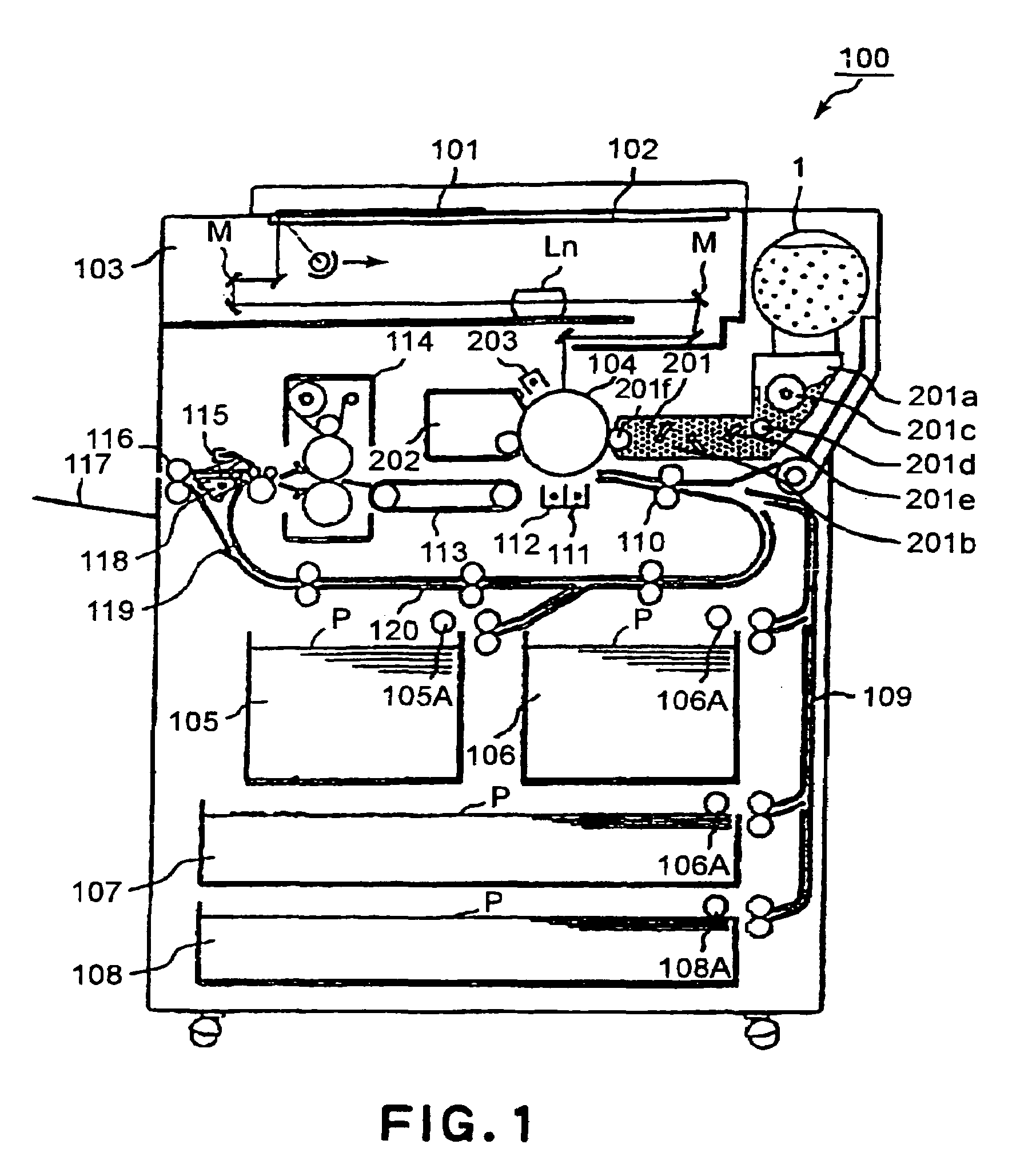
[0037]First, referring to FIG. 1, the structure of an electrophotographic image forming apparatus, as an example of an image forming apparatus in which a developer supply container in accordance with the present invention, will be described. As an original 101 is placed on the original placement glass platen 102 of the main assembly 100 of the electro-photographic copying machine (which hereinafter will be referred to as “apparatus main assembly”) shown in FIG. 1, the optical image (image formation data) of the original 101 is formed on the electrophotographic photosensitive drum, as an image bearing member, by the plurality of mirrors M and lenses Ln. Meanwhile, the cassette which contains the correct recording medium (which hereinafter may be simply referred as “sheets”) is selected from among sheet cassettes 105–108 in the main assembly, based on the sheet size information, that its, the information inputted by a user thr...


PUM


Abstract

A developer supply container detachably mountable to an image forming apparatus, the container includes a container body for accommodating the developer; drive connection member, provided substantially at a rotation center of the developer supply container, for driving engagement with a driving member provided in the image forming apparatus, wherein the drive connection member has a drive transmitting portion for transmitting a rotational force received from the driving member to the container body, wherein the drive transmitting portion is disposed so as to be idly rotatable for a sufficient time after start of rotation of the drive transmitting portion and before engagement with the container body.

Description

FIELD OF THE INVENTION AND RELATED ART[0001]The present invention relates to a developer supply container removably mountable in an image forming apparatus in order to supply the image forming apparatus with developer. Here, an image forming apparatus means an apparatus, such as a copying machine, a printer, a fax, etc., for forming images with the use of an electrophotographic or electrostatic recording method. The present invention also relates to a member with which a developer supply container is provided in order to coupling the developer supply container with the main assembly of the image forming apparatus, and also, to driving the container.[0002]Developer (toner) in the form of an extremely minute particle has been in use as developer for an electrophotographic image forming apparatus such as an electrophotographic copying machine or printer. It has been common practice that as the toner in the main assembly of an electrophotographic image forming apparatus is consumed, the...

Claims


Application Information

Patent Timeline
Patent Type & Authority Patents(United States)
IPC IPC(8): G03G15/00G03G15/08B65D83/06G03G15/06
CPCB65D83/06G03G15/0868G03G15/0872G03G15/0886B65D2231/005Y10S222/01G03G15/06
Inventor YAMADA, YUSUKE
Owner CANON KK
Why Eureka
Try Eureka