Method and device for transportation

A technology of conveying direction and conveying parts, which is applied in the field of conveying, and can solve the problems of insufficient high-speed and stable conveying of articles, wrinkling, etc.

Inactive Publication Date: 2002-03-06
ZUIKO CORP
View PDF3 Cites 44 Cited by
  • Summary
  • Abstract
  • Description
  • Claims
  • Application Information

AI Technical Summary

Problems solved by technology

[0006] However, when a soft workpiece having a certain length or width is conveyed by the above-mentioned conventional technology, such as sanitary products, it may wrinkle when it is transferred between rotating parts such as a drum and a drum, and thus cannot sufficiently satisfy high-speed and stable processing. Requests to send items

Method used


Image

  • Method and device for transportation
  • Method and device for transportation
  • Method and device for transportation

Examples


Embodiment Construction

[0038] An embodiment of the present invention will now be described with reference to the drawings.

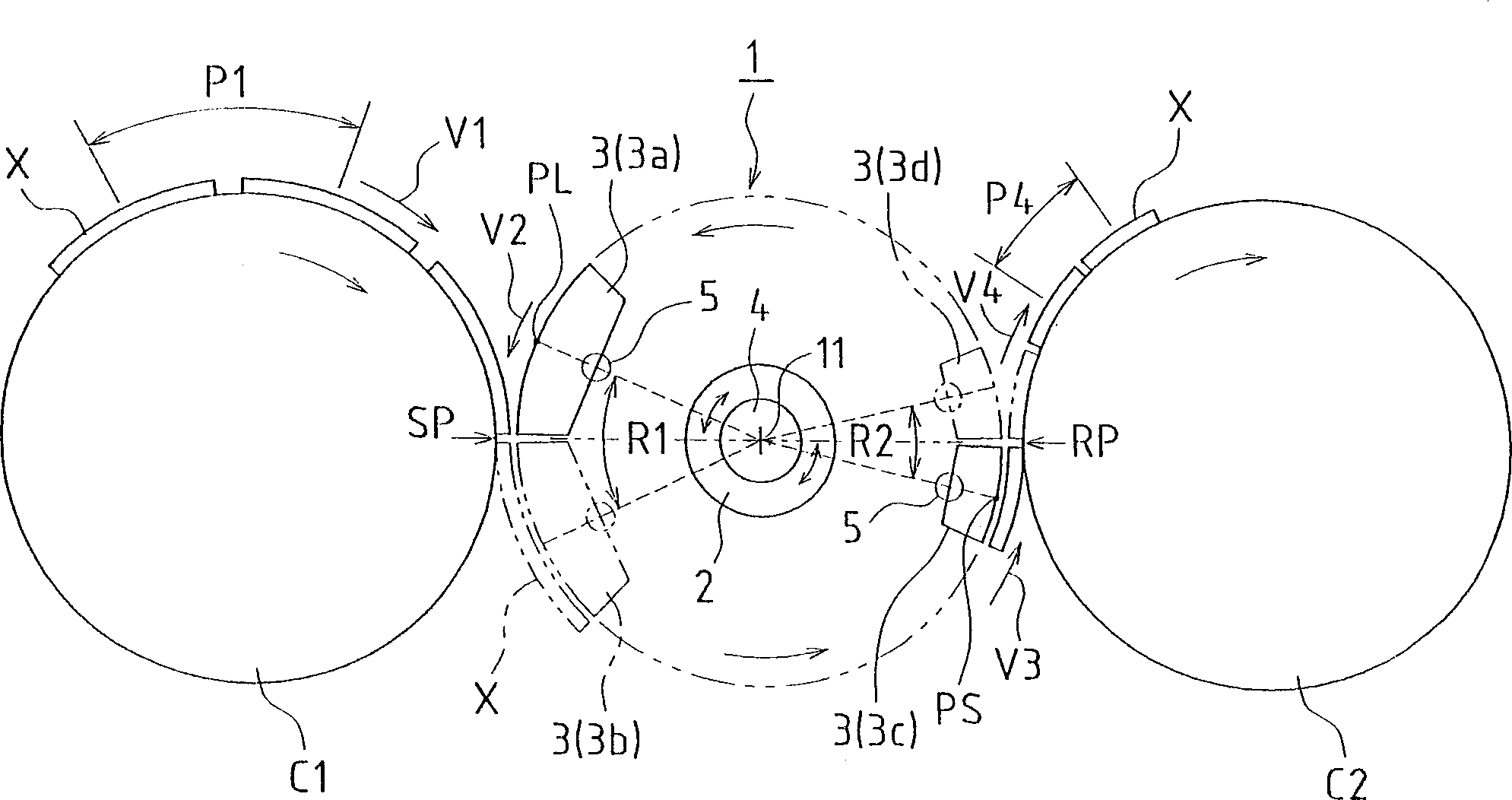
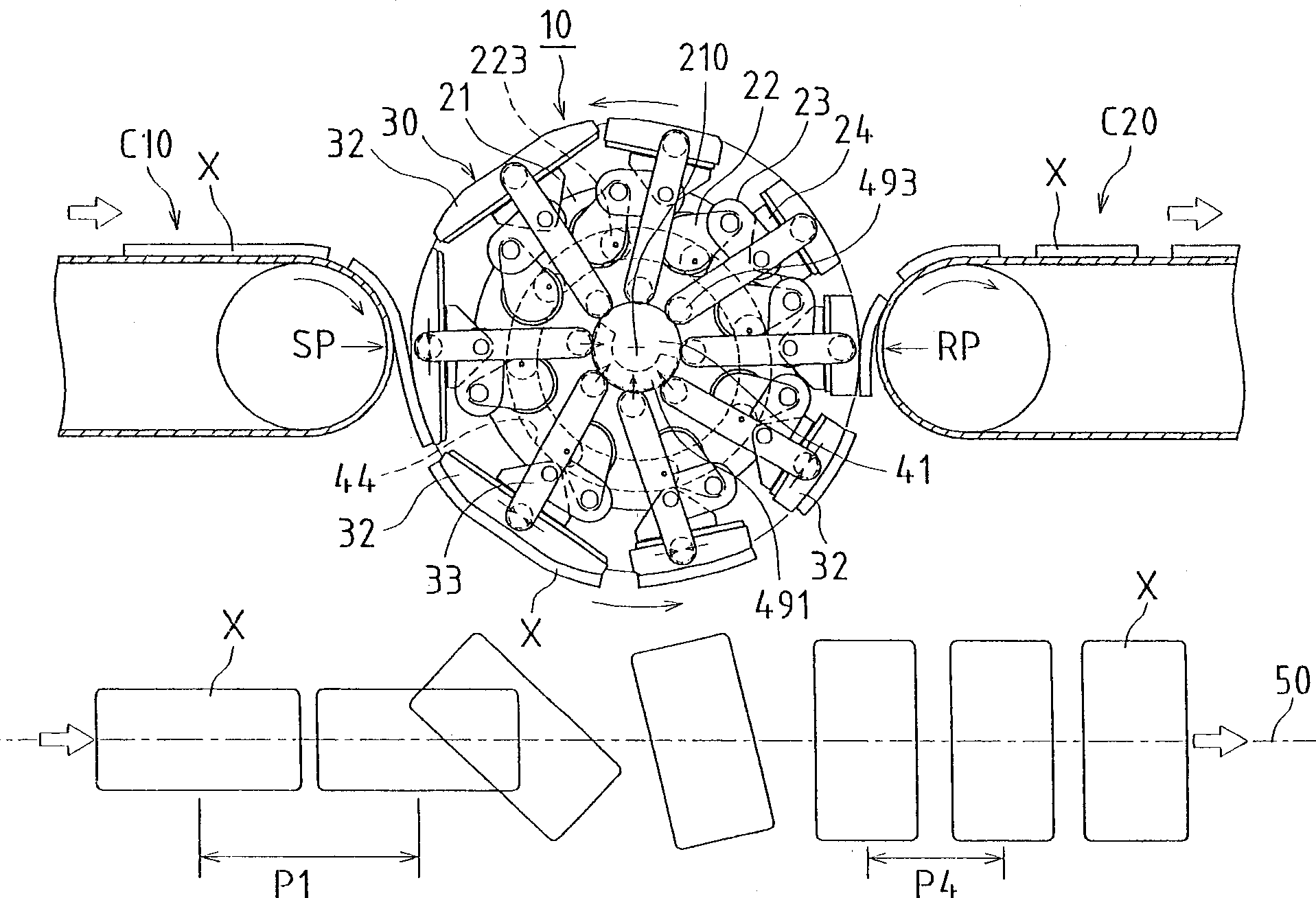
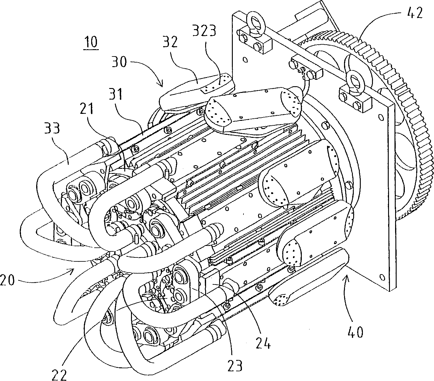
[0039] Figure 2 to Figure 4 The operation and general structure of the delivery device 10 according to the invention is shown. The conveying device 10 includes a substantially cylindrical rotor that can rotate around a rotating shaft 210 and is disposed between the previous conveyor belt C10 and the rear conveyor belt C20 . Both the shown front conveyor belt C10 and the rear conveyor belt C20 carry light and soft workpiece X (such as hygienic products such as sanitary napkins) on the air-permeable conveyor belt, and use vacuum suction to absorb workpiece X and continuously convey it Artifact X. The part that attracts the workpiece X is not limited to vacuuming but can be any other attracting part, which is electrostatic attraction. The conveying parts of the previous stage and the latter stage can be drums or other devices instead of conveyor belts.

[0040] In this embod...


PUM


Abstract

A transportation device (10) comprising crank arms (22) installed rotatably on a drive wheel (21), link levers (23) each having one end pin-connected to the tip of each of the crank arms (22), and swing parts (30) each having the other end pin-connected to each of the link levers (23) and held at a specified distance from a rotating shaft (210) of the drive wheel (21), wherein a speed changing cam roller (223) is installed on the crank arm (22) projectedly at a position apart from the rotating center thereof, and the transmission cam roller (223) is engaged for guiding with a transmission cam groove (44) formed eccentrically with respect to the rotating shaft (210) of the drive wheel (21), whereby the tips of the crank arms (22) are swung with in one rotation frequency of the drive wheel (21), and the angular velocities of the link levers and the swing part (30) connected thereto are increased or decreased periodically relative to the angular velocity of the drive wheel (21).

Description

technical field [0001] The invention relates to a conveying method, which can increase or decrease the conveying speed when moving workpieces (including materials) on one conveying belt are handed over to another conveying belt, and relates to conveying equipment with acceleration / deceleration function. Background technique [0002] Japanese Patent No. 2580493 discloses a device for cutting sanitary products and increasing the conveying pitch of the cut sanitary products. Specifically, the punching machine drum that cuts and conveys the hygiene products transfers the sanitary products to the transfer drum, which rotates at a higher peripheral speed than the punching machine drum, so that the conveying pitch of the sanitary products on the transfer surface of the transfer drum is greater than that of the punching drum. The transmission pitch of sanitary products on the transmission surface of the machine drum. [0003] Japanese Laid-Open Patent No. 63-317576 discloses a meth...

Claims


Application Information

Patent Timeline
Patent Type & Authority Applications(China)
IPC IPC(8): A61F13/15B65G47/244B65G47/84
CPCB65H2301/33216B65G47/244B65H2406/3454A61F13/15764B65G47/848
Inventor 中门正毅
Owner ZUIKO CORP
Why Eureka
Try Eureka