Supercharge Your Innovation With Domain-Expert AI Agents!

Illuminating brick

a technology of illumination bricks and bricks, applied in the field of illumination bricks, can solve the problems of insufficient illumination of the entire surface, and may not be practical or desirable to be positioned adjacent to the paved surface of lighting fixtures

Inactive Publication Date: 2011-12-20
FOXSEMICON INTEGRATED TECH INC
View PDF14 Cites 5 Cited by
  • Summary
  • Abstract
  • Description
  • Claims
  • Application Information

AI Technical Summary

Benefits of technology

"The patent describes an illuminating brick that has a light-emitting element embedded in it. The brick has a top, bottom, and sides, and the light-emitting element is connected to the bottom or sides. The sides and bottom reflect and direct the light emitted from the element so that it exits through the top of the brick. The technical effect of this invention is an illuminating brick that can provide lighting in a unique and interesting way."

Problems solved by technology

However, the light cast from a fixture may only illuminate a portion of the surface adjacent to the fixture and may not sufficiently illuminate the entire surface.
Moreover, lighting fixtures may not be practical or desirable to be positioned adjacent to the paved surface to provide the needed light because of natural or man-made obstacles.

Method used


Image

  • Illuminating brick
  • Illuminating brick
  • Illuminating brick

Examples


Embodiment Construction

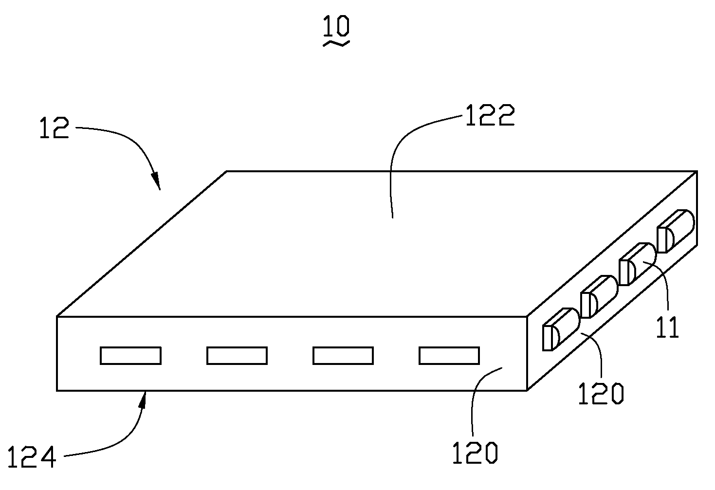
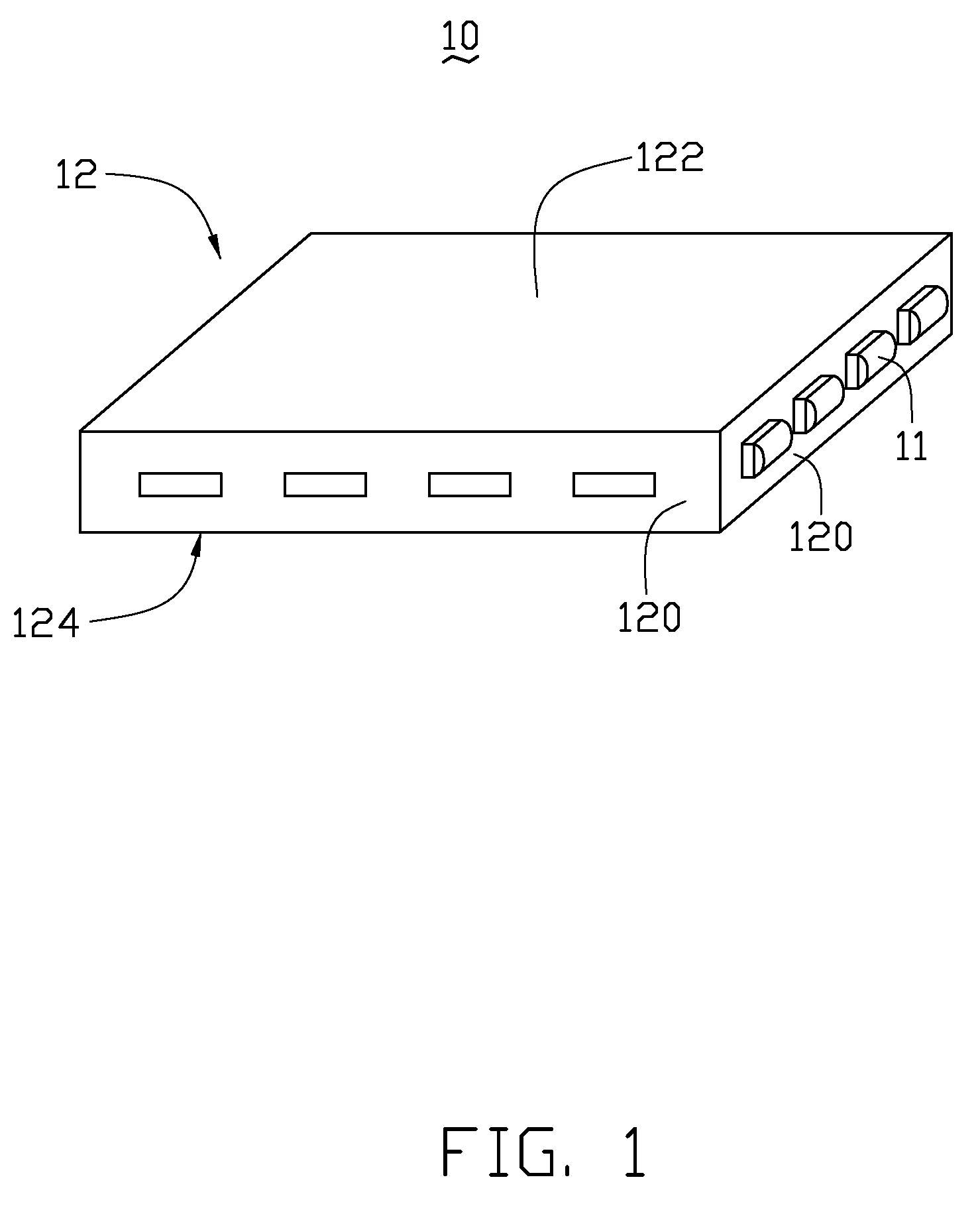
[0013]Referring to FIG. 1, an illuminating brick 10 can be used as unit pavers, stepping stone, ceramic tile etc. and comprises a brick 12 and a plurality of LED components 11 as light sources embedded in the brick 12.

[0014]The brick 12 optically coupling with the LED components 11, is made of transparent material such as tempered glass, polymethylmethacrylate, poly carbonate and silicone etc. The brick 12 can be made in any variety of shapes and sizes. In the present embodiment, the brick 12 is cuboid-shaped and includes a top face 122, a bottom face 124 opposite to the top face 122, and four lateral sides 120. In the first exemplary embodiment, the bottom face 124 is configured for being disposed on a relatively flat surface such as graded soil. The LED components 11 are embedded in and optically coupled to at least one of the four lateral sides 120. Light emitted by the LED components 11 diffuses into the brick 12 through the corresponding lateral side 120 and is then internally ...


PUM


Abstract

An illuminating brick includes a block and at least one light-emitting element mounted in the brick. The brick has a top face, a bottom face and a plurality of lateral side surfaces interconnecting the top and bottom faces. The at least one light-emitting element is engaged in and optically coupled to at least one of the bottom face and lateral side surfaces. The lateral side surfaces and the bottom face are configured for reflecting and directing light emitted from the at least a light-emitting element to exit through the top face.

Description

BACKGROUND[0001]1. Field of the Invention[0002]The present invention relates to an illuminating brick and particularly to an illuminating brick using LED components as light source.[0003]2. Description of Related Art[0004]Cast concrete paving components are often referred to as unit pavers when installed abutted or in quantity covering large areas and as stepping stones when installed in strings or individual to form a narrow pathway or walk way. The use of unit pavers and the stepping stones for covering soil or loose surface to provide walkways, pathways, floors or road surfaces is well known. Typically, unit pavers and stepping stones are designed have an attractive appearance as well as being functional. The most common unit pavers and stepping stones are constructed from cast concrete or pressure formed aggregates to provide a heavy weight, hard surface and durable paver or stepping stone, as needed. In addition to being functional, unit pavers and stepping stones are versatile...

Claims


Application Information

Patent Timeline
Patent Type & Authority Patents(United States)
IPC IPC(8): F21V7/04
CPCF21V33/006F21V5/02F21V13/04F21Y2101/02F21Y2115/10
Inventor TSAO, CHIH-CHUNGHSIEH, SHU-HUILIN, MEI-JIUNYANG, HUNG-CHIHCHEN, PING-YULEE, TSE-AN
Owner FOXSEMICON INTEGRATED TECH INC
Features
  • R&D
  • Intellectual Property
  • Life Sciences
  • Materials
  • Tech Scout
  • Unparalleled Data Quality
  • Higher Quality Content
  • 60% Fewer Hallucinations
Learn More