

Shielded cable
a shielding cable and shielding technology, applied in the direction of insulated conductors, power cables, cables, etc., can solve the problems of affecting the gain of the antenna, the resonance frequency varies by the length of the connected set ground gnd, and the antenna portion has a very complicated structure, etc., to achieve excellent design properties and low cost
Active Publication Date: 2011-12-20
SONY CORP
View PDF8 Cites 17 Cited by
- Summary
- Abstract
- Description
- Claims
- Application Information
AI Technical Summary
Benefits of technology
The present invention provides a shielded cable which can realize a shielded antenna cable which is low in cost and is excellent in design property and flexibility.
According to the embodiment of the present invention, a shielded antenna cable which is low in cost and is excellent in design properties and flexibility can be realized.
Problems solved by technology
Therefore, in this antenna, there is a fear that the fact that resonance frequency varies by the length of the connected set ground GND will become a problem.
Also, since the set ground GND also contributes to the radiation of the antenna, in a case such as mobile communication which is used with held by a human body, since the set ground GND is grasped, there is a fear that the gain of the antenna will be affected.
Also, in the above-described sleeve antenna, the coaxial cable is used only for a signal transmission function and an antenna portion has a very complicated structure.
Method used
View moreImage
Smart ImageViewing Examples

Examples
first embodiment (
1. A first embodiment (a first structure example of a shielded cable),
second embodiment (
2. A second embodiment (a second structure example of a shielded cable),
third embodiment (
3. A third embodiment (a first configuration example of an antenna device),
Login to View More PUM
 Abstract
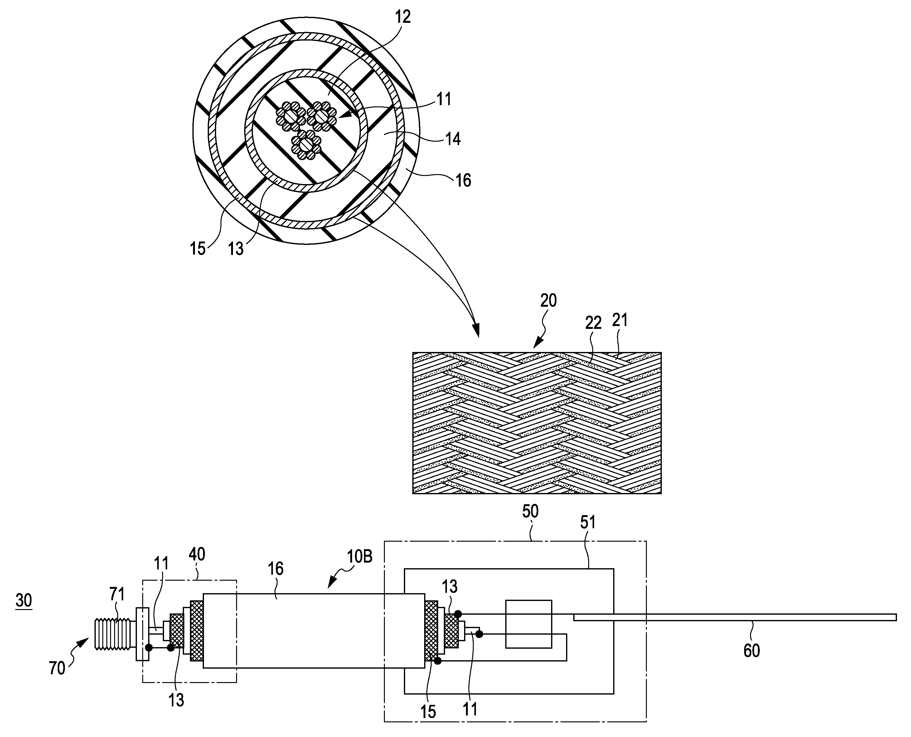
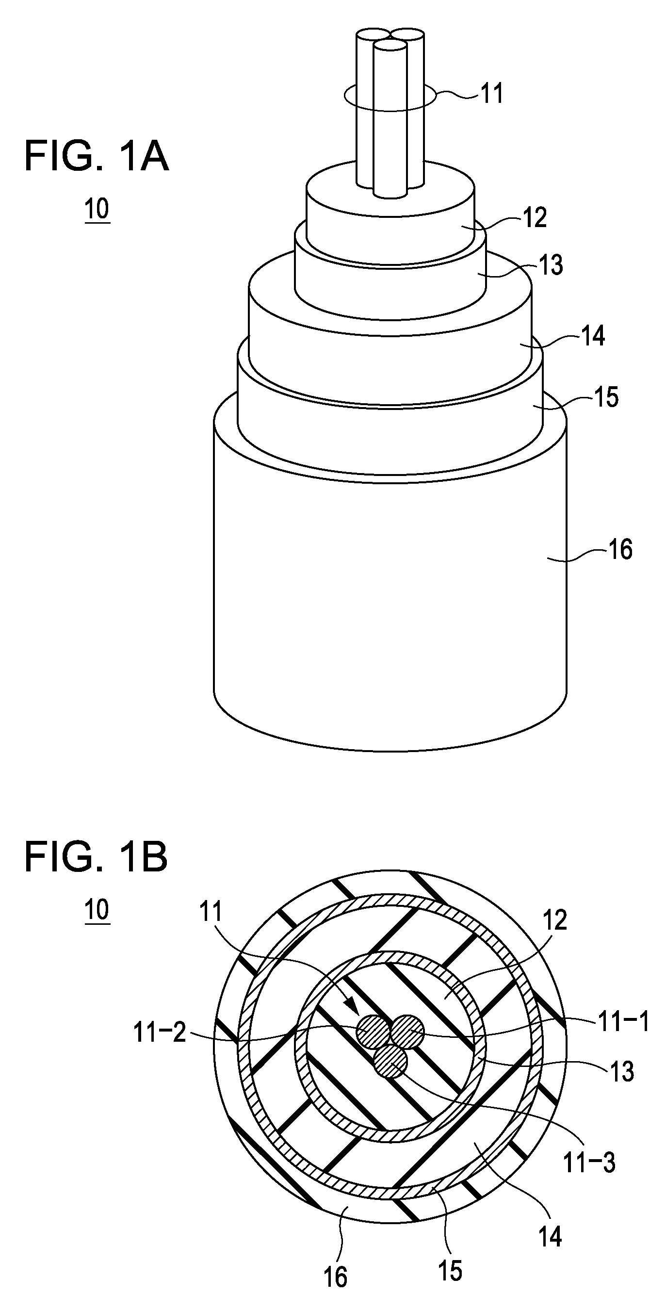
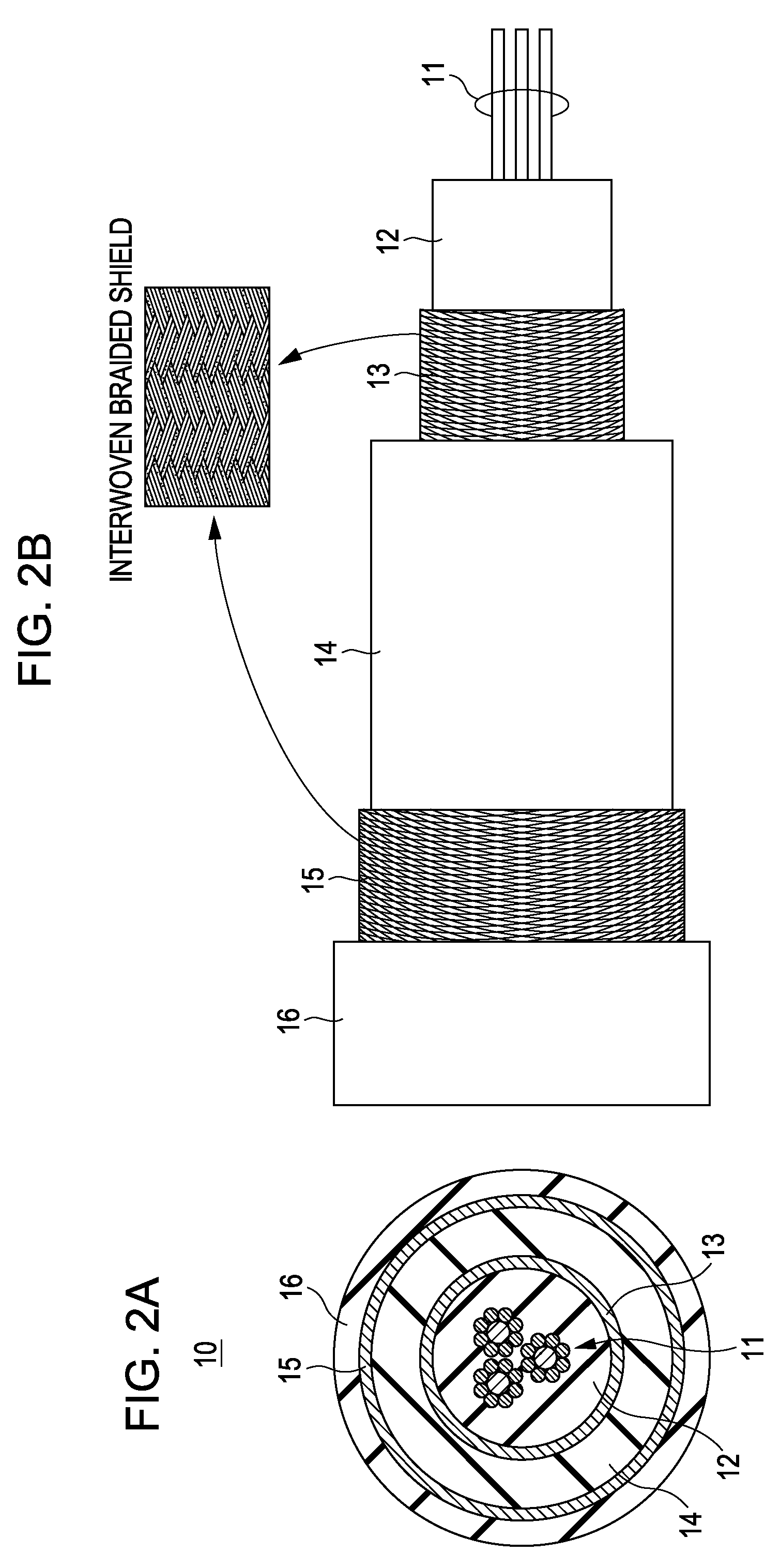
A shielded cable includes an inner conductor, a first insulator, a first outer conductor, a second insulator, and a second outer conductor, which are coaxially disposed in this order from an inner side, and has an outer circumference coated by an insulation sheath.
Description
BACKGROUND OF THE INVENTION1. Field of the InventionThe present invention relates to a shielded cable having flexibility which is applicable to portable electronic devices such as portable AV equipment and mobile telephones.2. Description of the Related ArtIn the field of consumer electronic products, there is AV equipment typified by portable sound reproduction equipment, and so on, and there is also a case where the sound of the equipment itself is heard through earphones (including headphones) using a coaxial cable.In recent years, a portable television receiver has been also developed, and there is also a case where the sound thereof is heard through earphones the earphones. A cable for earphones is formed by a shielded cable and also used in the transmission of a high-frequency signal of a receiving antenna or the like.In this manner, the technology of using an earphones cable as an antenna has been proposed.This kind of cable is used in order to transmit an audio signal (low f...
Claims
Login to View More Application Information
Patent Timeline
 Patent Type & AuthorityPatents(United States)
IPC IPC(8): H01R4/00
CPCH01Q9/30H01Q9/16H01B11/206H01B11/1808H01B11/1878
InventorMUKAI, KOICHIYOSHINO, YOSHITAKAKOMORI, CHISATO
OwnerSONY CORP