Supercharge Your Innovation With Domain-Expert AI Agents!

Control system for reciprocating device

a technology of control system and reciprocating device, which is applied in the direction of non-mechanical valves, valve details, reversing gears, etc., can solve the problems of stalling and becoming stuck of reciprocating devices

Inactive Publication Date: 2011-12-27
PLAINSMAN MFG
View PDF7 Cites 0 Cited by
  • Summary
  • Abstract
  • Description
  • Claims
  • Application Information

AI Technical Summary

Benefits of technology

"The invention is a control system for a reciprocating device that can move in two directions. The system includes a switching valve that can connect different parts of the device for fluid pressure. There is also a toggle that can be moved to different positions to control the flow of fluid. The system also includes means for actuating the toggle based on the direction of movement of the device. The actuation means use biasing forces to move the toggle to different positions and store energy while doing so. The technical effect of this invention is to provide a more efficient and precise control system for reciprocating devices."

Problems solved by technology

At low operating speeds and low operating pressures, the reciprocating devices can stall and become stuck as the operating valve passes through the middle position.

Method used


Image

  • Control system for reciprocating device
  • Control system for reciprocating device
  • Control system for reciprocating device

Examples


Embodiment Construction

[0021]The present invention relates to a control system for a fluid-driven reciprocating device. When describing the present invention, all terms not defined herein have their common art-recognized meanings. To the extent that the following description is of a specific embodiment or a particular use of the invention, it is intended to be illustrative only, and not limiting of the claimed invention. The following description is intended to cover all alternatives, modifications and equivalents that are included in the spirit and scope of the invention, as defined in the appended claims.

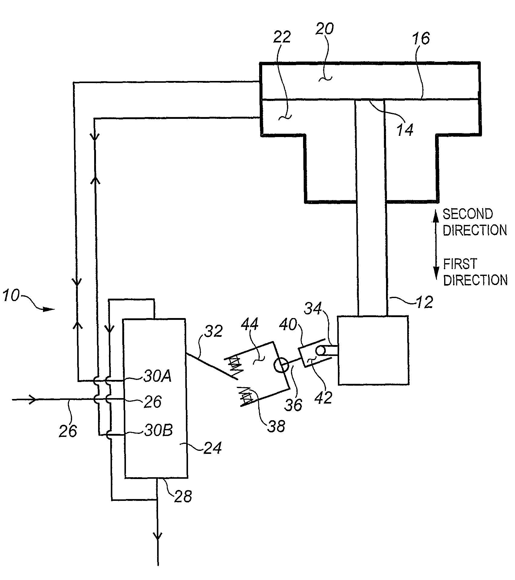
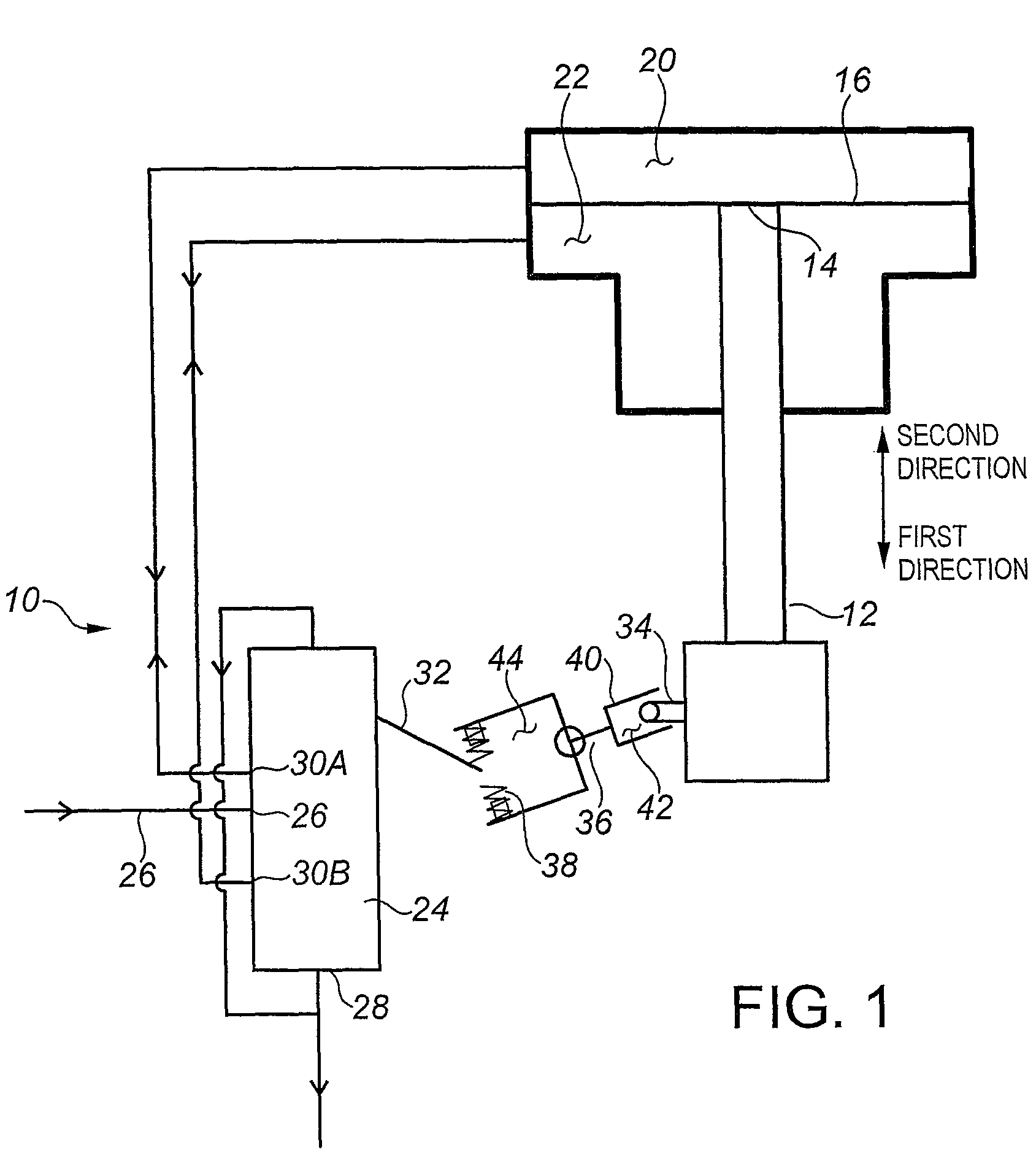
[0022]In one embodiment shown schematically in FIG. 1, the invention comprises a control system (10) for a reciprocating device. The reciprocating device has a linearly reciprocating shaft (12) which reciprocates between a first direction and a second direction opposed to the first direction. The first end (14) of the shaft is connected to a platen (16). The platen (16) divides a fluid retaining chamber...


PUM


Abstract

A control system for a reciprocating device includes a switching valve, a toggle for operating the valve, a trigger associated with the reciprocating device to actuate the toggle, and biasing means disposed on the trigger for applying a biasing force to the toggle. The valve includes a first drive line, a second drive line, a fluid supply inlet and a fluid exhaust outlet. The valve switches between the first and second drive lines upon actuation of the toggle by the trigger, to switch direction of the reciprocating device.

Description

CROSS REFERENCE TO RELATED APPLICATIONS[0001]This application claims the priority benefit of U.S. Provisional Patent Application No. 60 / 972,830 filed on Sep. 17, 2007 entitled “Control System for Reciprocating Device”, the contents of which are incorporated herein by reference.FIELD OF THE INVENTION[0002]The present invention relates to a control system for a reciprocating device for use in such applications as reciprocating drives, reciprocating actuators, reciprocating pumps, reciprocating power generators and other reciprocating devices commonly powered by fluid power.BACKGROUND[0003]Canadian Patent CA 2294410 (Lauder) and Canadian Patent Application CA 2493340 (Day) describe operational difficulties experienced by state of the art reciprocating devices used to power chemical injection pumps on oil and gas wells. At low operating speeds and low operating pressures, the reciprocating devices can stall and become stuck as the operating valve passes through the middle position. Laud...

Claims


Application Information

Patent Timeline
Patent Type & Authority Patents(United States)
IPC IPC(8): F01L29/06F04B53/10
CPCF15B21/12
Inventor LEA-WILSON, MARK
Owner PLAINSMAN MFG
Features
  • R&D
  • Intellectual Property
  • Life Sciences
  • Materials
  • Tech Scout
  • Unparalleled Data Quality
  • Higher Quality Content
  • 60% Fewer Hallucinations
Learn More