Photoreceptor unit and image forming apparatus

a photoreceptor and image forming technology, applied in the direction of electrographic process apparatus, instruments, corona discharge, etc., can solve the problem that the photoreceptor cannot be fully protected, and the problem of not necessarily solving fully, so as to facilitate convenient handling, save resources, and ensure the effect of sufficient protection

Active Publication Date: 2011-12-27
KONICA MINOLTA BUSINESS TECH INC
View PDF12 Cites 2 Cited by
  • Summary
  • Abstract
  • Description
  • Claims
  • Application Information

AI Technical Summary

Benefits of technology

[0010]An object of the present invention is to provide a photoreceptor unit which facilitates convenient handling at the time of exchange, allows sufficient protection of a photoreceptor and also allows resource saving, and an image forming apparatus provided with the photoreceptor unit.
[0016]According to one embodiment, in the above-described photoreceptor unit, a flange portion is formed at an end of the rigid cover, and the flange portion is capable of preventing the photoreceptor unit equipped with the rigid cover from being excessively inserted into the image forming apparatus.
[0022]According to one embodiment, a flange portion is formed at an end of the rigid cover, and the flange portion is capable of preventing the photoreceptor unit equipped with the rigid cover from being excessively inserted into the image forming apparatus.
[0024]According to the present invention, a photoreceptor unit facilitating convenient handling at the time of exchange, allowing sufficient protection of a photoreceptor and also allowing resource saving can be provided, as will be hereinafter described in greater detail.
[0025]First, as a rigid cover and a cushioning member are provided on a photoreceptor, the photoreceptor can be protected from the pressure applied by the user's operation. In this case, the portion of the photoreceptor that is not provided with the rigid cover is covered with a light-shielding sheet, which allows the photoreceptor to be protected from light. The rigid cover employed as a grip can facilitate convenient handling at the time when the photoreceptor is exchanged. As the rigid cover is provided in the photoreceptor unit on the front side in the insertion direction and the light-shielding sheet is provided on the rear side thereof in such a manner that the rigid cover and the light-shielding sheet can be removed together, it becomes possible to grip the rigid cover and insert the photoreceptor into the image forming apparatus without removing the light-shielding sheet. Furthermore, resource saving can also be achieved as compared with the case where the photoreceptor is covered entirely in the axial direction with the rigid cover.

Problems solved by technology

However, it is not preferable in terms of resource saving to provide a rigid cover on the entire photoreceptor drum.
Furthermore, the process cartridge disclosed in Document 2 aims at reducing distortion and sliding friction of a charging roll, and does not necessarily serve to fully solve the above-described problems.

Method used


Image

  • Photoreceptor unit and image forming apparatus
  • Photoreceptor unit and image forming apparatus
  • Photoreceptor unit and image forming apparatus

Examples


Embodiment Construction

[0038]The embodiments of the present invention will be hereinafter described with reference to the accompanying drawings, in which the same or corresponding components are designated by the same reference characters, and description thereof may not be repeated.

[0039]With regard to the embodiments described below, in the case where reference is made to the number of elements, amount or the like, the scope of the present invention is not necessarily limited thereto unless otherwise specified. Also in the embodiments described below, each component is not necessarily essential to the present invention unless otherwise specified.

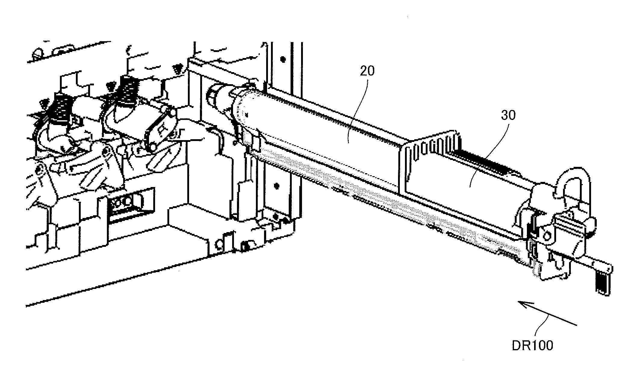
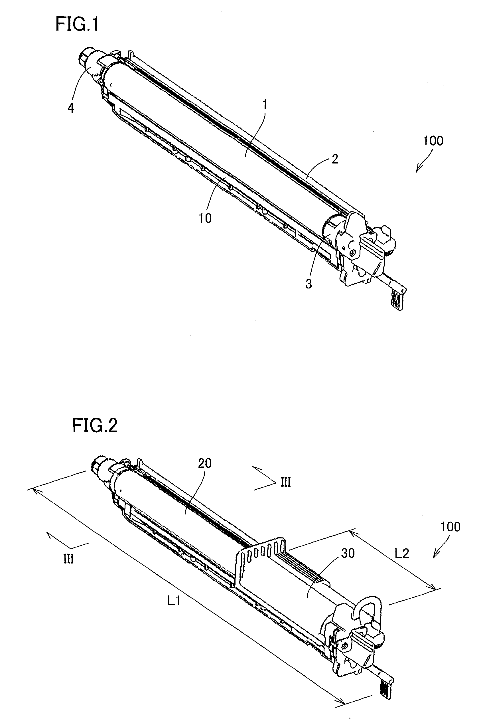
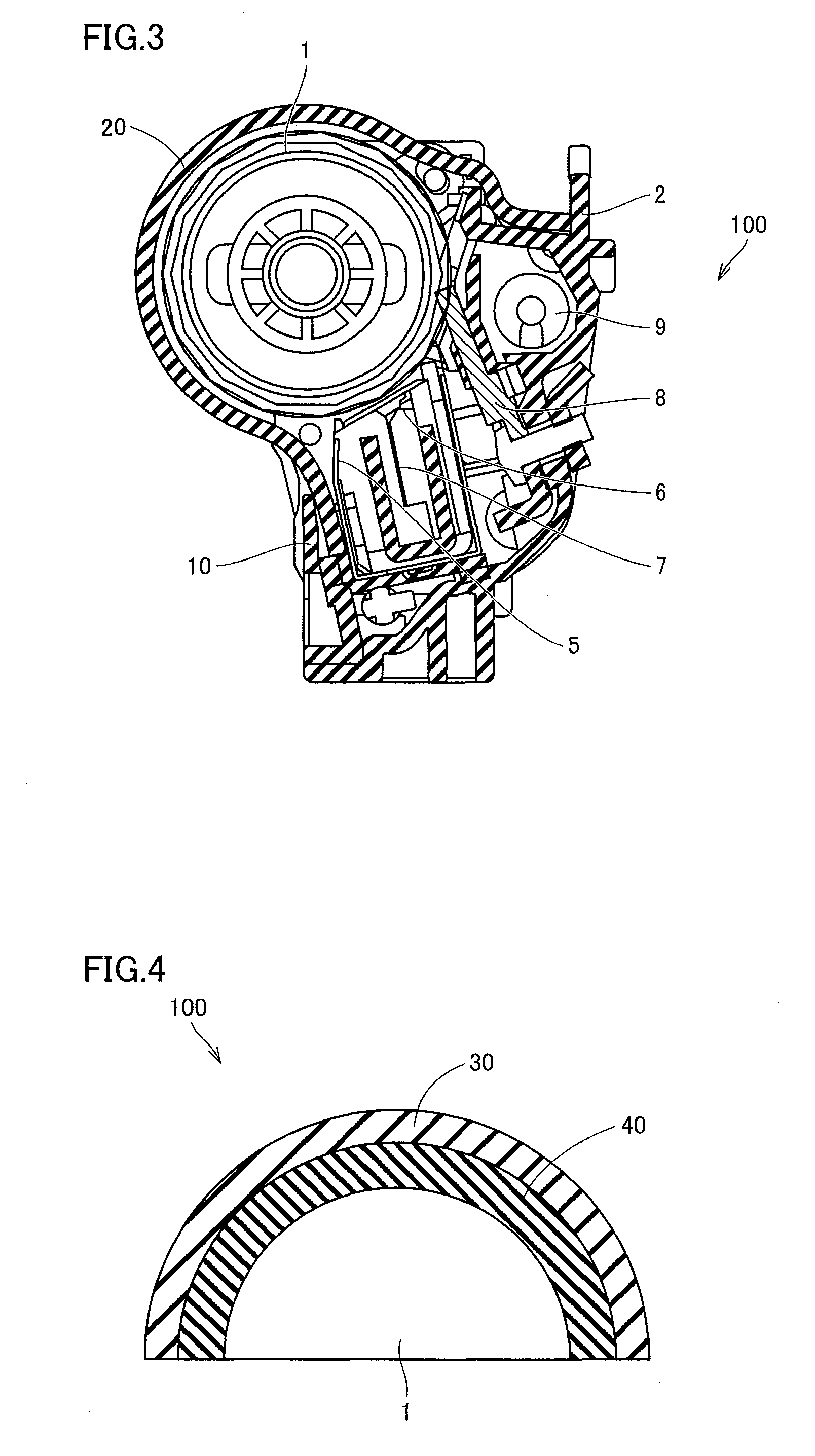
[0040]FIG. 1 is a diagram showing the state after removal of the packaging material of a photoreceptor unit 100 according to one embodiment of the present invention. FIG. 2 is a diagram showing the state before removal of the packaging material of photoreceptor unit 100. FIG. 3 is a cross sectional view of photoreceptor unit 100 taken along line III-III in FIG. ...


PUM


Abstract

A photoreceptor unit is inserted into an image forming apparatus in the predetermined insertion direction, and includes a photoreceptor, a light-shielding sheet covering a part of the photoreceptor on the front side in the insertion direction; a rigid cover made of resin and provided adjacent to the light-shielding sheet on the rear side in the insertion direction; and a cushioning member interposed between the rigid cover and the photoreceptor. The rigid cover has a length that allows the photoreceptor unit to be gripped at the rigid cover. The light-shielding sheet, the rigid cover and the cushioning member can be removed together from the photoreceptor.

Description

[0001]This application is based on Japanese Patent Application No 2008-311002 filed with the Japan Patent Office on Dec. 5, 2008, the entire content of which is hereby incorporated by reference.BACKGROUND OF THE INVENTION[0002]1. Field of the Invention[0003]The present invention relates to a photoreceptor unit and an image forming apparatus, and particularly to a photoreceptor unit inserted into an image forming apparatus in a predetermined insertion direction and the image forming apparatus.[0004]2. Description of the Related Art[0005]Japanese Laid-Open Patent Publication No. 2006-267808 (Document 1) discloses a process cartridge for a printer and the like provided with a cover member having a two-layered structure which includes a cushioning sheet protecting a photoreceptor drum and shielding the photoreceptor drum from light, and a cover sheet removed from a cartridge body together with the cushioning sheet at the time when the cartridge body strikes against the external wall of ...

Claims


Application Information

Patent Timeline
Patent Type & Authority Patents(United States)
IPC IPC(8): G03G21/16
CPCG03G21/1832
Inventor HAYASHI, HIDEJI
Owner KONICA MINOLTA BUSINESS TECH INC
Why Eureka
Try Eureka