

Machine having an improved draining grid for compacting humid waste
a technology of humid waste and draining grid, which is applied in the direction of filtration separation, manufacturing tools, separation processes, etc., can solve the problems of screw arresting total and sometimes even damage, and achieve the effect of continuing to work and without any danger of damag
- Summary
- Abstract
- Description
- Claims
- Application Information
AI Technical Summary
Benefits of technology
Problems solved by technology
Method used
Image

Examples
Embodiment Construction
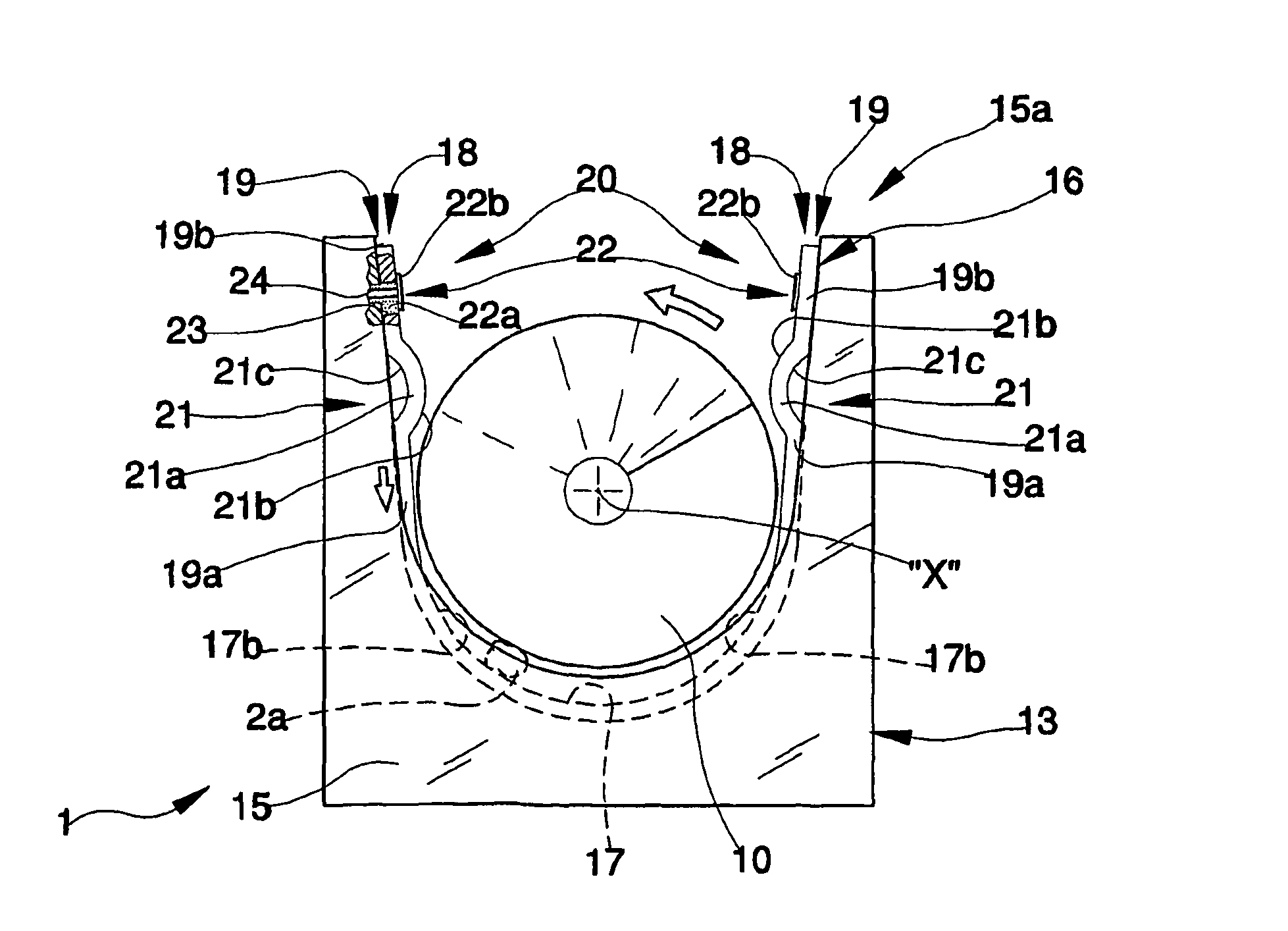
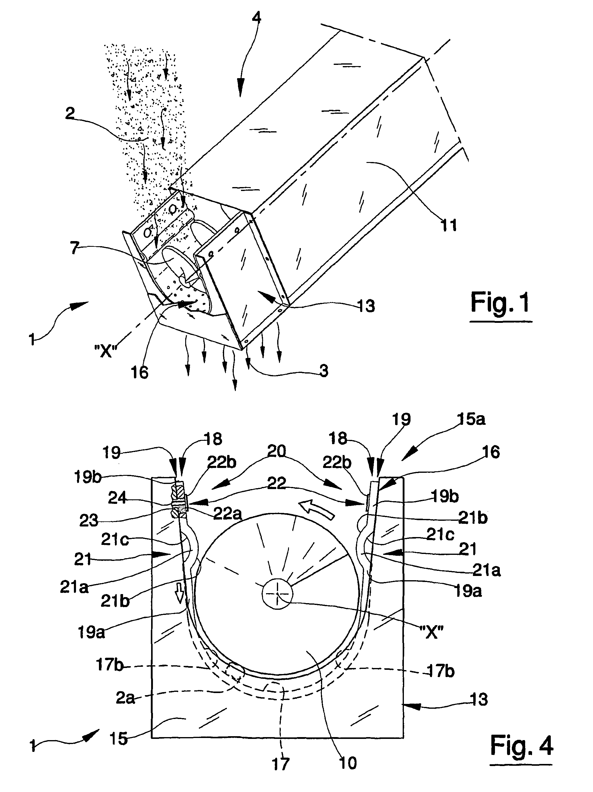
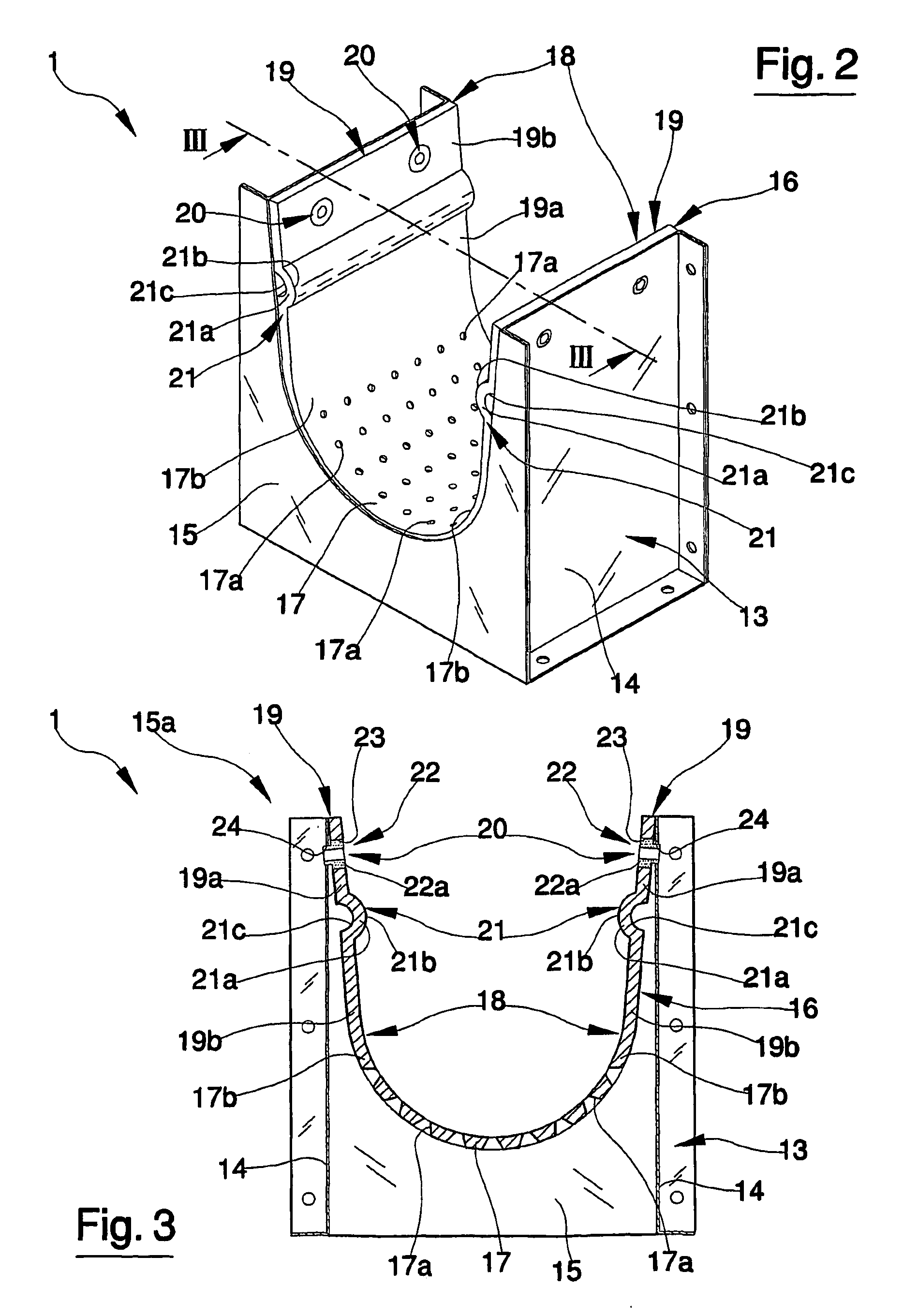
[0016]With reference to the figures of the drawings, 1 denotes in its entirety a drainage grid of a machine 4 destined for compacting humid waste.
[0017]As with known-type machines, the machine 4 comprises an Archimedes screw 7 which is rotated about a longitudinal axis X thereof by a motor (not illustrated in the figures) internally of a containing structure 11. The drainage grid 1 of the machine comprises a perforated structure 16 which exhibits at least an arched portion 17 which is predisposed to adhere against the helix 10 of the screw 7. The screw 7, which can be of any type, for example with or without a central shaft, is generally, though not necessarily, predisposed to rise in order to transport the solid waste in an upwards direction.
[0018]The humid waste 2 is introduced into the machine usually by means of a hopper (not illustrated); the rotation of the screw 7 enables the helix thereof to take and draw the solid substances present in the waste upwards; the liquids 3 conta...
PUM
| Property | Measurement | Unit |
|---|---|---|
| force | aaaaa | aaaaa |
| area | aaaaa | aaaaa |
| rotation | aaaaa | aaaaa |
Abstract
Description
Claims
Application Information