
Method and apparatus for eliminating or reducing waste effluent from a wet electrostatic precipitator

a technology of wet electrostatic precipitator and waste effluent, which is applied in the direction of electrode cleaning, chemistry apparatus and processes, transportation and packaging, etc., can solve the problems of high cost of operation of centrifuge and evaporator system, the cost of supplying fresh makeup water, and the cost of treating and/or disposing of waste effluent can be substantial, so as to reduce the requirement of quench water makeup, reduce the requirement of fresh makeup water, and reduce the effect of bleed

Active Publication Date: 2012-01-10
ZENVIRO TECH HLDG INC
View PDF11 Cites 4 Cited by
  • Summary
  • Abstract
  • Description
  • Claims
  • Application Information

AI Technical Summary

Benefits of technology

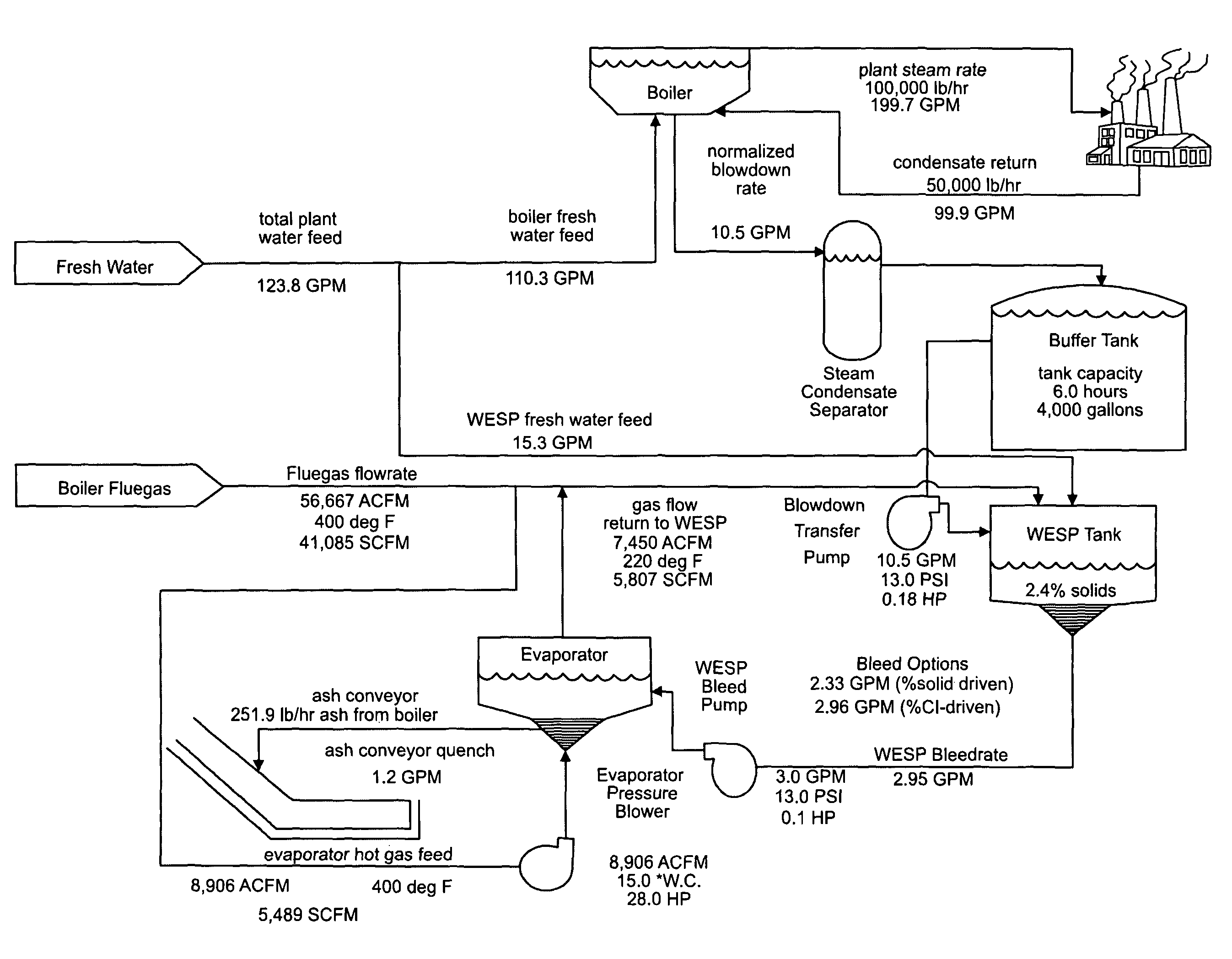
[0006]In one embodiment, a method is provided for reducing waste effluent from a system including a boiler and a wet electrostatic precipitator, the waste effluent comprising blow down water discharged from the boiler during a blow down operation and bleed water discharged by the wet electrostatic precipitator. The method includes collecting the blow down water and providing the collected blow down water to the wet electrostatic precipitator as a makeup water supplement, thereby simultaneously reusing the blow down water and reducing the fresh makeup water requirement for the wet electrostatic precipitator.
[0007]In another embodiment, a method is provided for reducing the bleed water waste effluent from a wet electrostatic precipitator. The method comprises evaporating at least a portion of the bleed water. Using flue gas to evaporate the bleed water would further reduce the quench water makeup requirement of the wet-electrostatic precipitator, thereby simultaneously reducing the bleed water waste effluent and reducing the fresh makeup water requirement for the wet electrostatic precipitator.
[0008]In yet another embodiment, a method is provided for reducing to zero the waste effluent from a system including a boiler and a wet electrostatic precipitator, the waste effluent comprising blow down water discharged by the boiler during a blow down operation and bleed water discharged by the wet electrostatic precipitator. The method comprises collecting the blow down water, providing the collected blow down water to the wet electrostatic precipitator as a makeup water supplement, evaporating a portion of the bleed water and leaving residual bleed water, and using the residual bleed water to quench ash produced by combustion of solid fuel by the boiler, thereby reducing to zero the waste effluent from the system. Using flue gas to evaporate the bleed water would further reduce the quench water makeup requirement of the wet electrostatic precipitator.
[0009]In still another embodiment, an apparatus is provided for reducing waste effluent from a system including a boiler and a wet electrostatic precipitator, the waste effluent comprising blow down water discharged by the boiler and bleed water discharged by the wet electrostatic precipitator. The apparatus comprises an evaporator for evaporating at least a portion of the bleed water. Using flue gas to evaporate the bleed water would further reduce the quench water makeup requirement of the wet electrostatic precipitator.

Problems solved by technology

Disadvantages of these prior methods for disposal of the bleed water include, but are not limited to, problems with environmental permit compliance (especially for zero liquid discharge facilities) and high cost of operation for centrifuge and evaporator systems.
For a system of industrial scale, the cost of supplying the fresh makeup water and the cost of treating and / or disposing of the waste effluent can be substantial.
The blow down water is waste effluent that typically must be treated and / or disposed of, again at a substantial cost due to the sheer quantity of waste effluent that is generated for a boiler of industrial scale.

Method used


Image

  • Method and apparatus for eliminating or reducing waste effluent from a wet electrostatic precipitator
  • Method and apparatus for eliminating or reducing waste effluent from a wet electrostatic precipitator
  • Method and apparatus for eliminating or reducing waste effluent from a wet electrostatic precipitator

Examples


Embodiment Construction

[0020]The following examples further illustrate the invention but, of course, should not be construed as in any way limiting its scope.

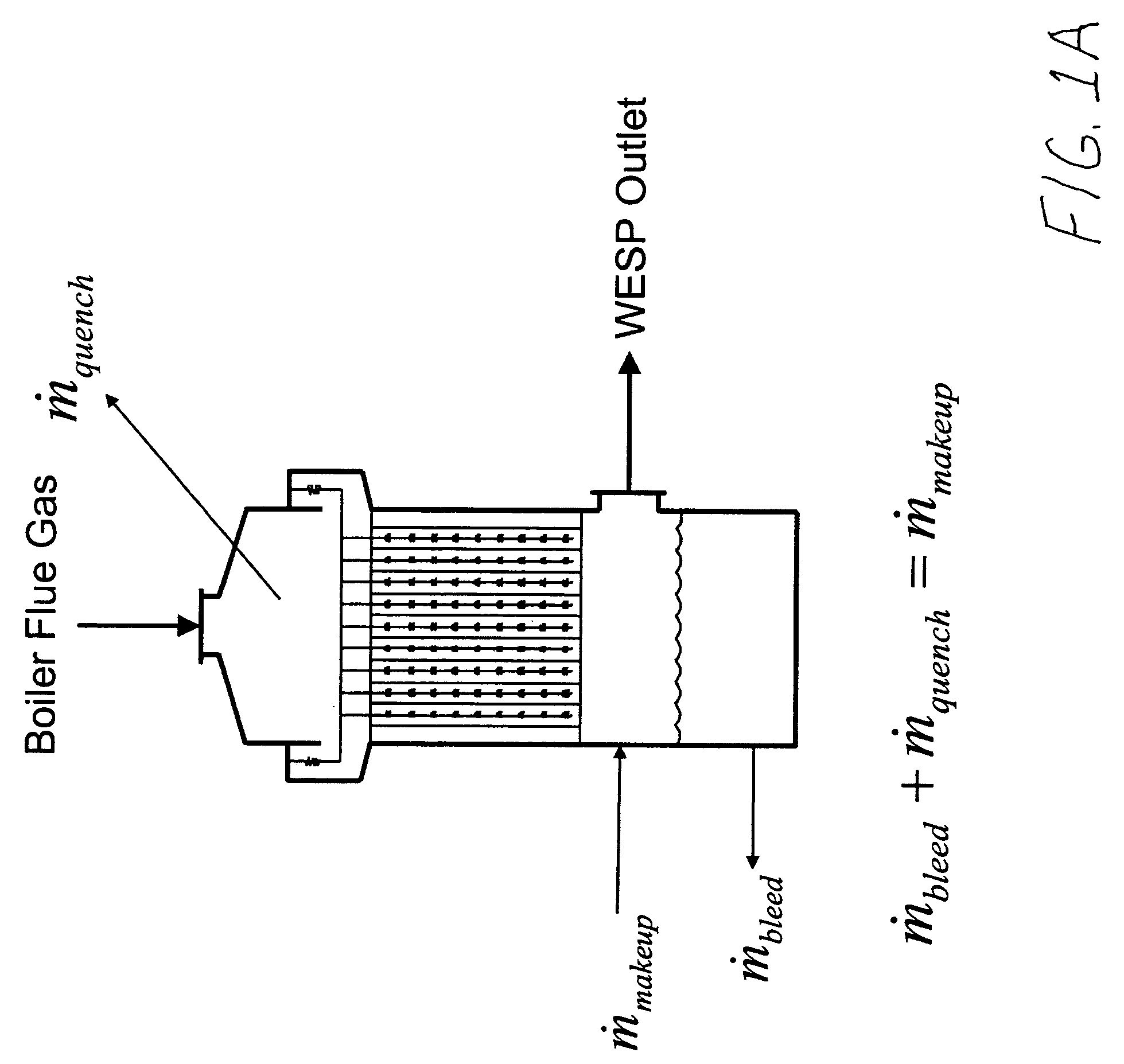
[0021]There is shown in FIG. 1A a schematic diagram and mass balance of water for an embodiment of a wet electrostatic precipitator (WESP). A boiler flue gas, containing particulates and possibly also containing acid gas, enters the WESP and is exposed to a spray of water which quenches the flue gas and assists in the removal of the particulates and scrubbing of the acid gas. As a result, a scrubbed flue gas emerges from the WESP. An amount of the water spray, denoted as mquench, evaporates as it quenches the flue gas and is carried out of the WESP in the scrubbed flue gas. Another amount of the water spray, denoted as mbleed, is discharged from the bottom of the WESP to remove accumulated settled, suspended or dissolved solids. (The water in the bottom of the WESP begins to form a sludge over time as particulate matter accumulates. Salts and chlorid...


PUM


Abstract

A method and apparatus are provided for reducing waste effluent from a system including a boiler and a wet electrostatic precipitator, the waste effluent having blow down water discharged by the boiler during a blow down operation and bleed water discharged by the wet electrostatic precipitator. The method includes collecting the blow down water and providing it to the wet electrostatic precipitator as a makeup water supplement, evaporating a portion of the bleed water and leaving residual bleed water, providing the evaporated bleed water to the wet electrostatic precipitator as a further makeup water supplement, and using the residual bleed water to quench ash produced by combustion of solid fuel by the boiler. The apparatus includes an evaporator that provides direct contact between hot boiler flue gas and the bleed water such that a portion of the flue gas is quenched before being provided to the wet electrostatic precipitator.

Description

FIELD OF THE INVENTION[0001]This invention pertains to a method and apparatus for reducing or eliminating the waste stream of water or sludge effluent from a wet electrostatic precipitator that is used to treat the flue gas from a solid fuel boiler.BACKGROUND OF THE INVENTION[0002]Many industrial processes utilize steam created by a boiler that is fed by a solid fuel such as coal, wood, biomass, or other similar material. Such fuels, when combusted, produce ash and other fine particulate matter as by-products which must be removed from the flue gas of the boiler prior to release of the flue gas to the atmosphere. Acid gas emissions may also be present. A wet electrostatic precipitator (WESP) is often used to remove particulate matter from the flue gas, in the presence or absence of acid gas emissions.[0003]As described, for example in U.S. Pat. Nos. 7,297,182 and 7,318,857, commonly owned with the present application, a wet electrostatic precipitator requires a supply of water for q...

Claims


Application Information

Patent Timeline
Patent Type & Authority Patents(United States)
IPC IPC(8): B03C3/014
CPCB03C3/017B03C3/16B03C3/014B03C2201/10B03C2201/08Y10T137/8593Y10T137/0318
Inventor SHULFER, JOSEPHVEIT, EBERHARD
Owner ZENVIRO TECH HLDG INC
Learn More