RFID detection and identification system for implantable medical devices

a medical device and detection system technology, applied in the field of rfid interrogation systems, can solve the problems of inability to reliably identify, inability to provide information, and inability to detect and identify patients, so as to facilitate rf communication and prevent entry

Inactive Publication Date: 2012-01-10
WILSON GREATBATCH LTD
View PDF12 Cites 197 Cited by
  • Summary
  • Abstract
  • Description
  • Claims
  • Application Information

AI Technical Summary

Problems solved by technology

The information so provided is limited due to space and typically includes only the manufacturer and model number of the implanted device.
For example, product recalls are an increasingly complex and extensive problem and the ability to rapidly identify the precise model and serial number of an implanted product may be life-saving.
However, such forms of identification are often not reliable.
In addition, there have been a number of situations where the patient (due to dementia or Alzheimer's, etc.) cannot clearly state that he or she even has a pacemaker.
If the patient is comatose, has low blood pressure, or is in another form of cardiac distress, this presents a serious dilemma for the physician.
What happens next is both laborious and time consuming.
All of the lost time running around to find the right programmer, however, may greatly delay or preclude this.
However, the primary problem with using such prior devices in humans has to do with the fact that none of the current RFID tags have been designed to have long term reliability and biocompatibility within the body fluid environment.
However, none of these materials provide a truly hermetic seal against body fluids.

Method used


Image

  • RFID detection and identification system for implantable medical devices
  • RFID detection and identification system for implantable medical devices
  • RFID detection and identification system for implantable medical devices

Examples


Embodiment Construction

[0037]As shown in the accompanying drawings for purposes of illustration, the present invention is related to systems and methods for providing RFID tags in a hermetically sealed manner so that a physician or other medical professional can identify and communicate with the RFID tag and ascertain information regarding the implanted medical device (IMD), patient, etc.

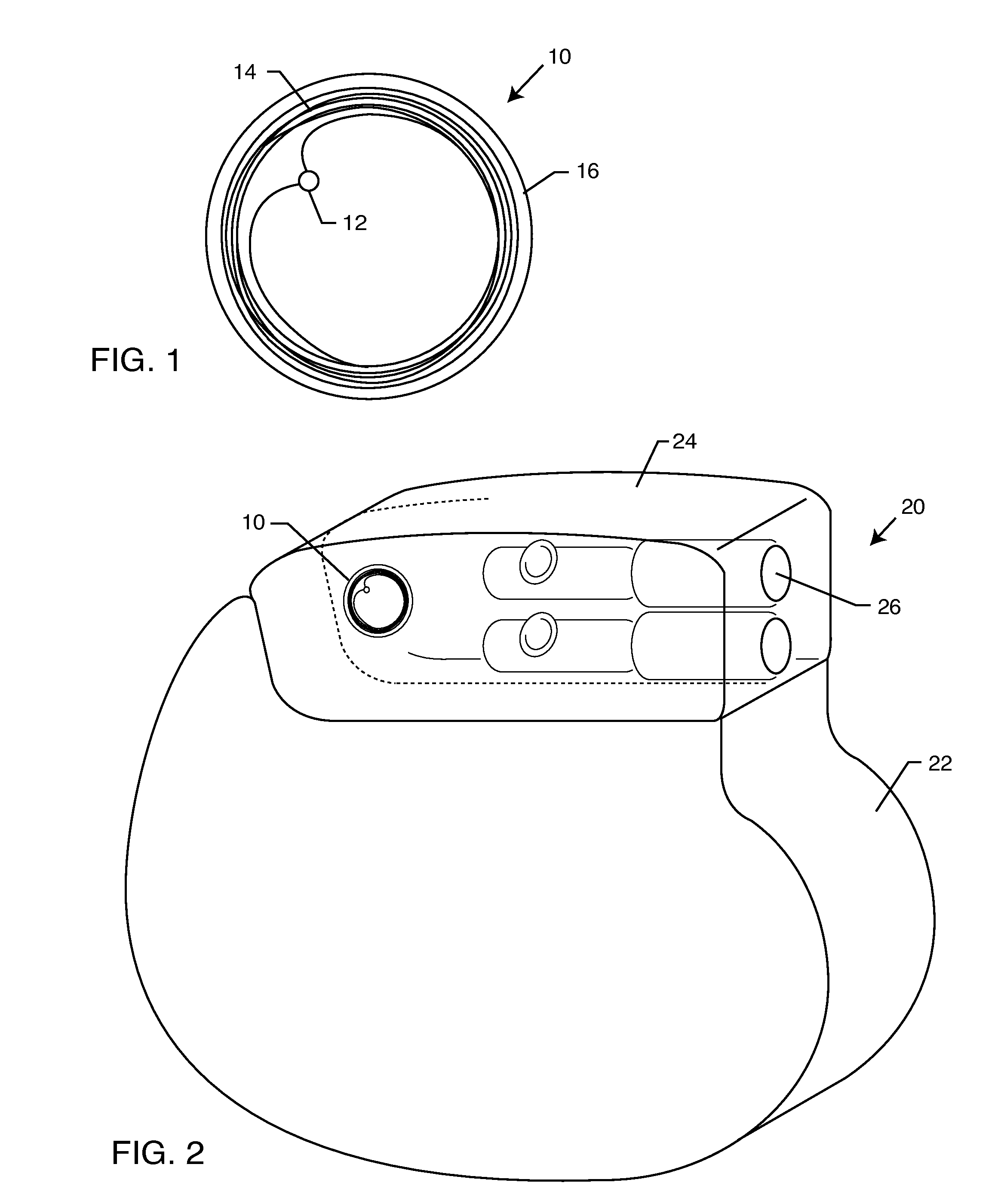
[0038]With reference now to FIG. 1, an exemplary prior art RFID tag 10 is shown. The RFID tag 10 includes a chip 12 which contains memory, and other electronic components and circuits necessary to store, send, and in some cases receive and store data in volatile memory. An antenna 14 is operably connected to the chip 12, and the chip 12 and antenna 14 are typically supported by a substrate or base 16. Such RFID tags are well known in the art.

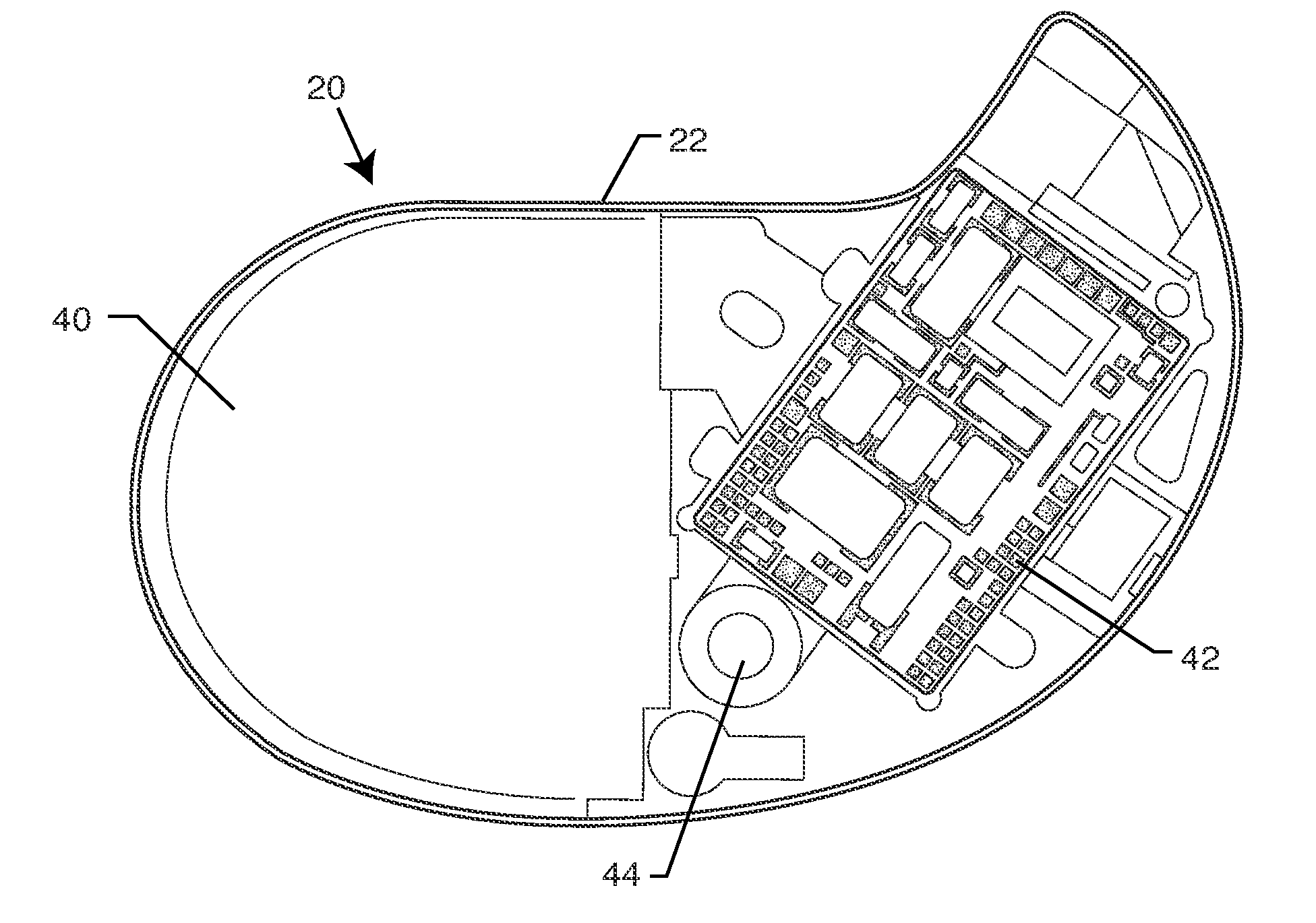
[0039]With reference now to FIG. 2, an IMD 20 is illustrated. In this case, the IMD 20 is a pacemaker or implantable cardioverter defibrillator (ICD). However, the present invention i...


PUM


Abstract

An RFID tag is disposed within a hermetically sealed housing of an IMD. Low frequency RFID interrogators and tags are used, and the housing walls are made of materials, and / or are reduced in thickness, to facilitate RF communication between the RFID tag and an RFID reader / interrogator programmer. An RFID reader / interrogator may be used which has a limited transmit time and time-out period to avoid interference with the operation of the IMD.

Description

BACKGROUND OF THE INVENTION[0001]The present invention generally relates to RFID interrogation systems and the ability to communicate with RFID tags associated with implantable medical devices (IMDs). More particularly, the present invention is directed to systems and methods for communicating with an RFID tag which is disposed in the hermetically sealed housing or can of the IMD.[0002]There are known in the art various methods for identifying implanted medical devices. One such method is the use of X-ray identification tags encapsulated within header blocks of pacemakers or implantable cardioverter defibrillators (ICD). Such X-ray identification tags can be read on an X-ray of the implanted device and provide information to the physician. The information so provided is limited due to space and typically includes only the manufacturer and model number of the implanted device.[0003]It would be beneficial if physicians were able to obtain additional information about an implanted devi...

Claims


Application Information

Patent Timeline
Patent Type & Authority Patents(United States)
IPC IPC(8): H04Q1/00
CPCG06K19/07758
Inventor STEVENSON, ROBERT A.TYERS, GEDDES FRANKTRUEX, BUEHL E.MUFFOLETTO, BARRY C.SPAULDING, JOSEPHKELLEY, SCOTT W.FRYSZ, CHRISTINE A.
Owner WILSON GREATBATCH LTD
Why Eureka
Try Eureka