Operating device

a technology of operating switch and hand, which is applied in the direction of identification means, instruments, television systems, etc., can solve the problems of difficult to grasp the distance between the operating switch and the hand, poor operability, etc., and achieve the effect of the same operability

Active Publication Date: 2012-01-10
TOYOTA JIDOSHA KK
View PDF55 Cites 11 Cited by
  • Summary
  • Abstract
  • Description
  • Claims
  • Application Information

AI Technical Summary

Benefits of technology

[0010]It is an object of the invention to provide an operating device that adopts a construction of the prompter system and is capable of securing substantially the same operability as that of the construction of the reflection system.
[0019]According to the invention, an operating device that adopts a construction of the prompter system and is able to secure substantially the same operability as that of the construction of the reflection system can be obtained.

Problems solved by technology

Therefore, the user operates the operation switches in the operating portion while looking at the image of the hand that appears as planar as the operation menu image, so that it is difficult to grasp the sense of the distance between an operating switch and the hand.
Thus, the operability is not very good.

Method used


Image

  • Operating device
  • Operating device
  • Operating device

Examples


second embodiment

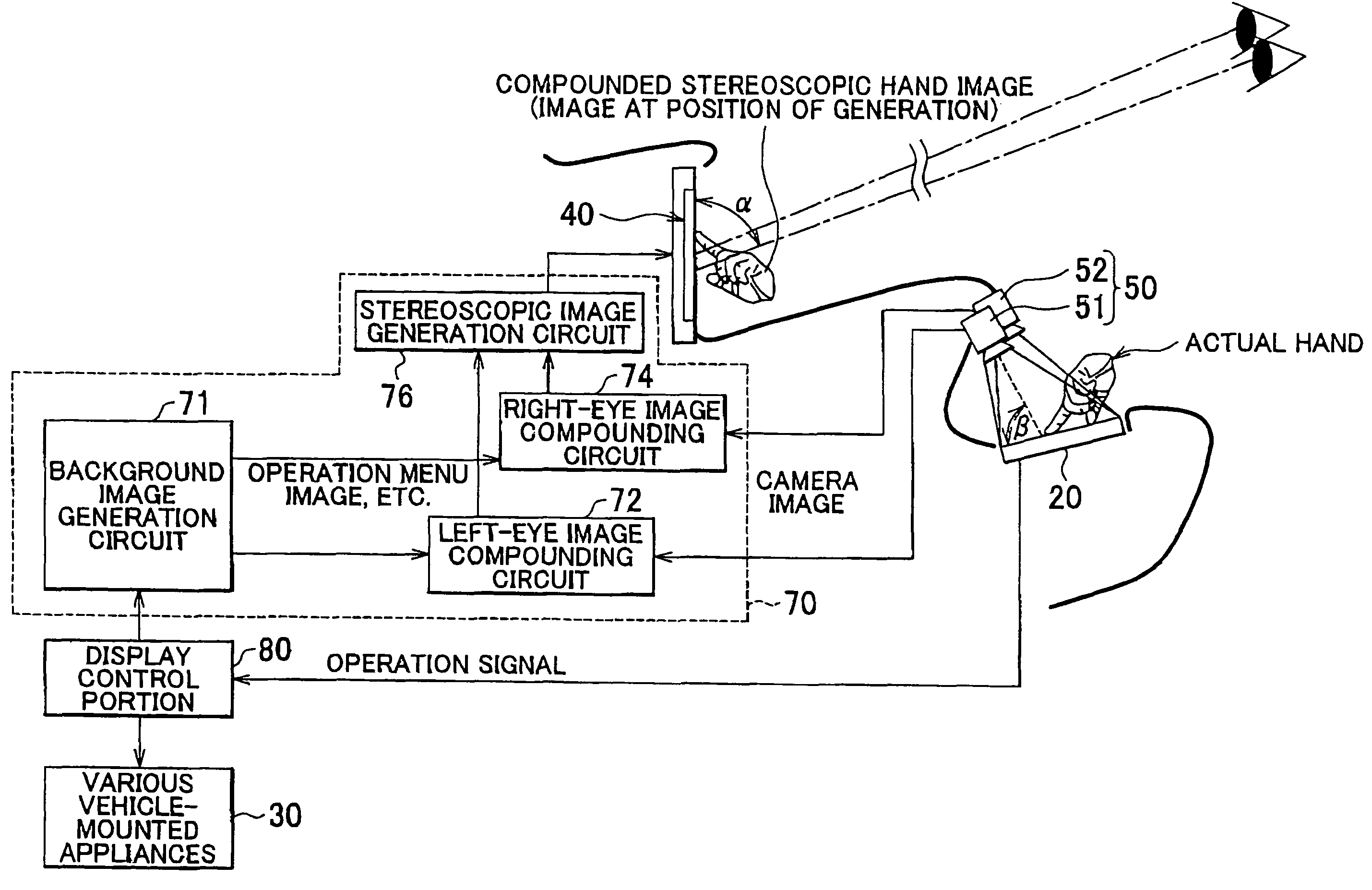
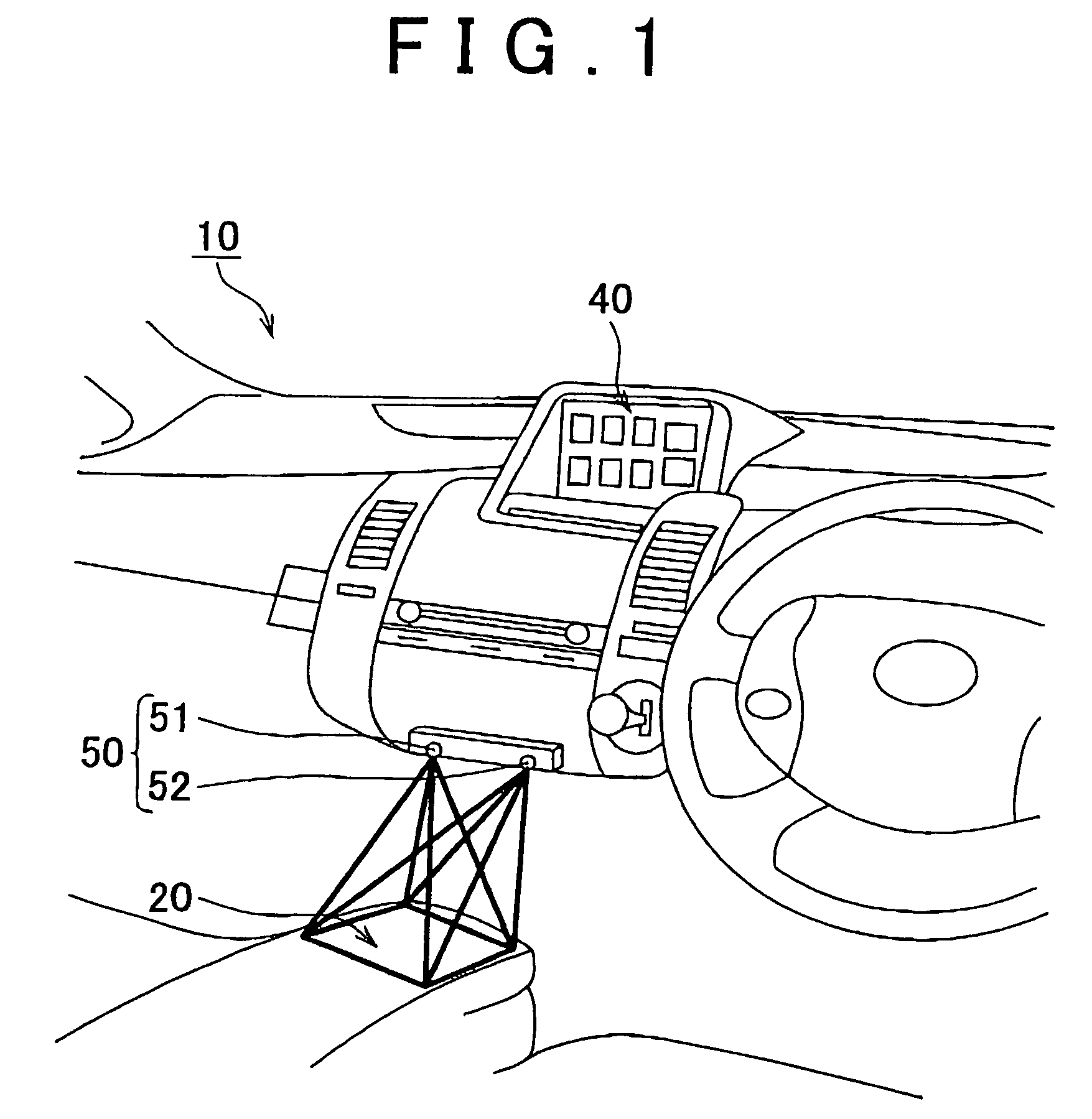
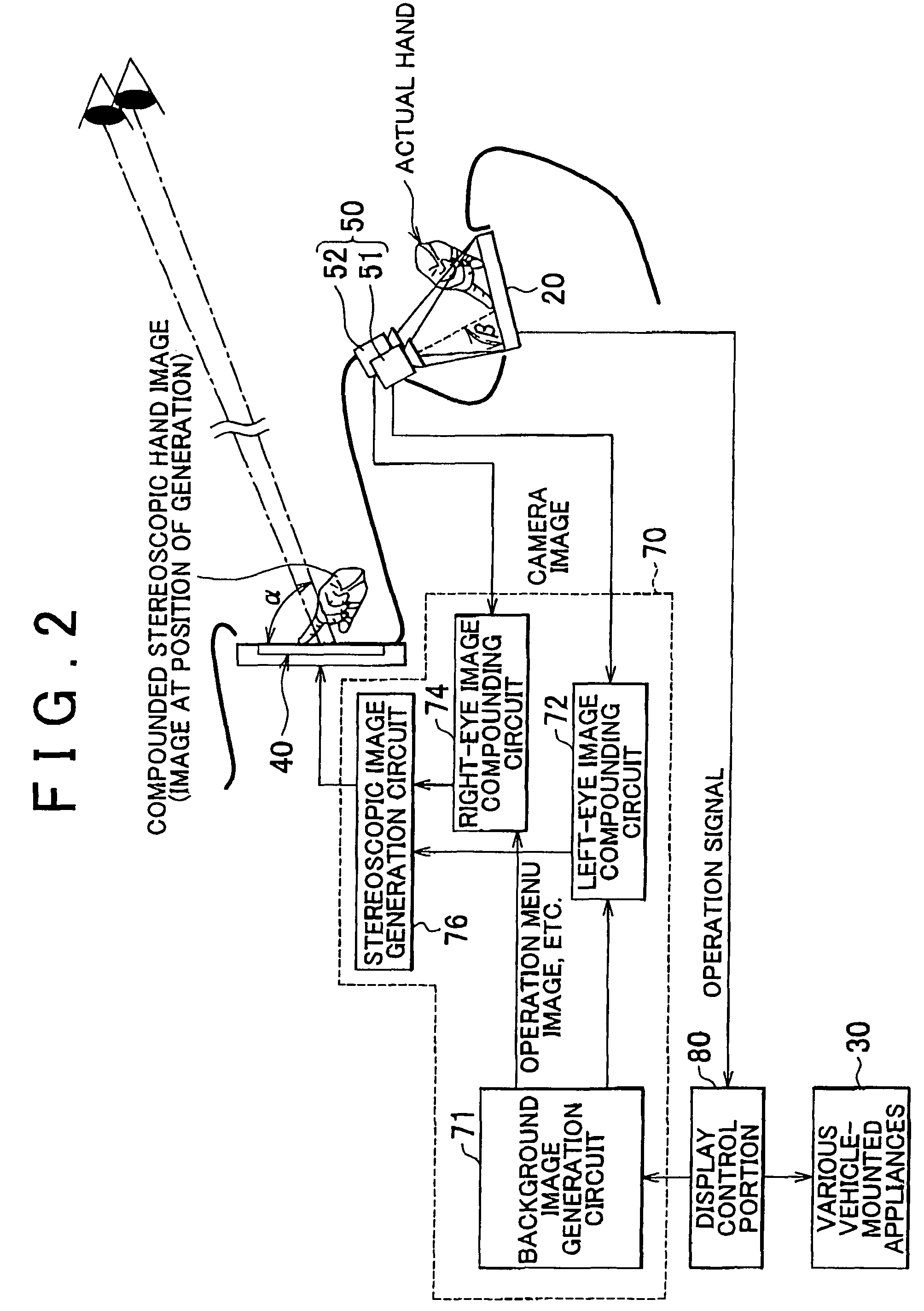
[0066]FIG. 7 is a perspective view showing the operating device 100 in accordance with the invention in a vehicle-mounted state as shown in second embodiment. FIG. 8 is a functional block diagram showing main functions of the operating device 100 shown in FIG. 7. In second embodiment, the constructions that may be the same as those in first embodiment are assigned with the same reference characters, and the descriptions thereof are omitted.

[0067]Second embodiment has main features in switching a camera image for use for the generation of a stereoscopic hand image in accordance with whether the operating portion 20 is being operated from the driver's seat side or the navigator's seat side. Hereinafter, constructions characteristic of second embodiment will be predominantly described.

[0068]A camera 500, as shown in FIG. 7, is a three-lens camera made up of three cameras 501, 502, 503 that are substantially linearly disposed apart from each other in a vehicle width direction. The camer...

third embodiment

[0079]Third embodiment is different from first and second Embodiments described above, in that the graphic images F1 to F8 in the operation menu image that represent operation switches are also stereoscopically displayed. The component elements that may be the same as those of first embodiment are assigned with the same reference characters, and the descriptions thereof will be omitted.

[0080]FIG. 12 is a diagrammatic side sectional view of an operating device 200 in accordance with third embodiment.

[0081]The background image generation circuit 710 generates a background image (an operation menu image in this case) to be displayed in the display portion 40, and supplies the generated background image to the left-eye image compounding circuit 72 and the right-eye image compounding circuit 74. In this embodiment, the background image generation circuit 710, as shown in FIG. 13, generates the graphic images F1 to F8 in the operation menu image that represent the operation switches in th...


PUM


Abstract

The invention relates to an operating device that includes: an operating portion in which an operation switch is disposed; a display portion that allows stereoscopic vision to be viewed by naked-eye; an image pickup mechanism that takes pictures of a hand of a user operating the operating portion, from a plurality of directions; and a displayed image generation device that generates a stereoscopic image of the hand based on parallax images obtained from the image pickup device. An operation menu image that depicts a position of the operation switch in the operating portion and a function of the operation switch, and a stereoscopic image of the hand generated by the displayed image generation device, and the compounded image is displayed in the display.

Description

INCORPORATION BY REFERENCE[0001]The disclosures of Japanese Patent Applications Nos. 2007-019788 filed on Jan. 30, 2007 and 2007-106011 filed on Apr. 13, 2007, each including the specification, drawings and abstract, are incorporated herein by reference in their entireties.BACKGROUND OF THE INVENTION[0002]1. Field of the Invention[0003]The invention relates to an operating device that superimposes an image of a hand of a user operating an operating portion on an operation menu image.[0004]2. Description of the Related Art[0005]There is a known vehicle-mounted appliances switch safety operating system characterized by including: a multifunction switch operation plate in which a plurality of kinds of switches for actuating or operating various vehicle-mounted appliances are arranged in a concentrated manner; a display that is disposed at a suitable position in the vehicle within a visual field region such that the operator can see the display by looking forward and that displays in it...

Claims


Application Information

Patent Timeline
Patent Type & Authority Patents(United States)
IPC IPC(8): H04N7/18G06F12/00
CPCB60K35/00B60K37/06B60K2350/2013B60K2350/2017B60K2370/21B60K2370/1531B60K2370/1526
Inventor KUMON, HITOSHI
Owner TOYOTA JIDOSHA KK
Why Eureka
Try Eureka