Pumped drainage apparatus

a technology of pumping apparatus and drainage pipe, which is applied in water installations, baths, constructions, etc., can solve problems such as intrusive operation noise and the possibility of undesirable odours backflowing into the shower area

Active Publication Date: 2012-01-17
DLP
View PDF20 Cites 4 Cited by
  • Summary
  • Abstract
  • Description
  • Claims
  • Application Information

AI Technical Summary

Benefits of technology

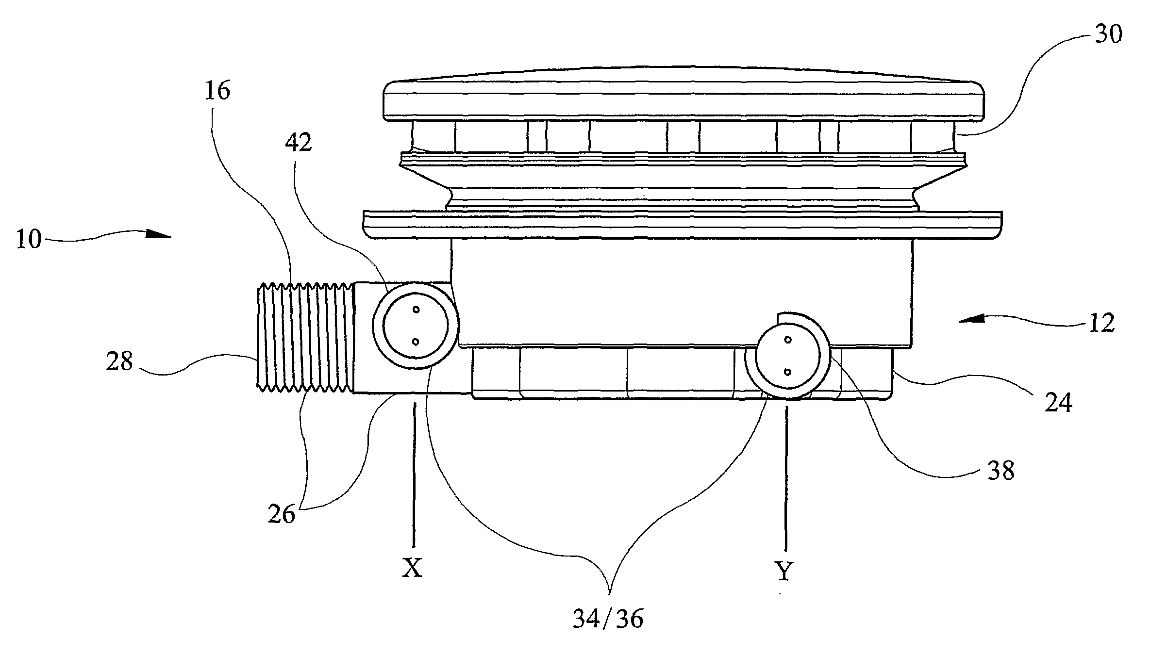
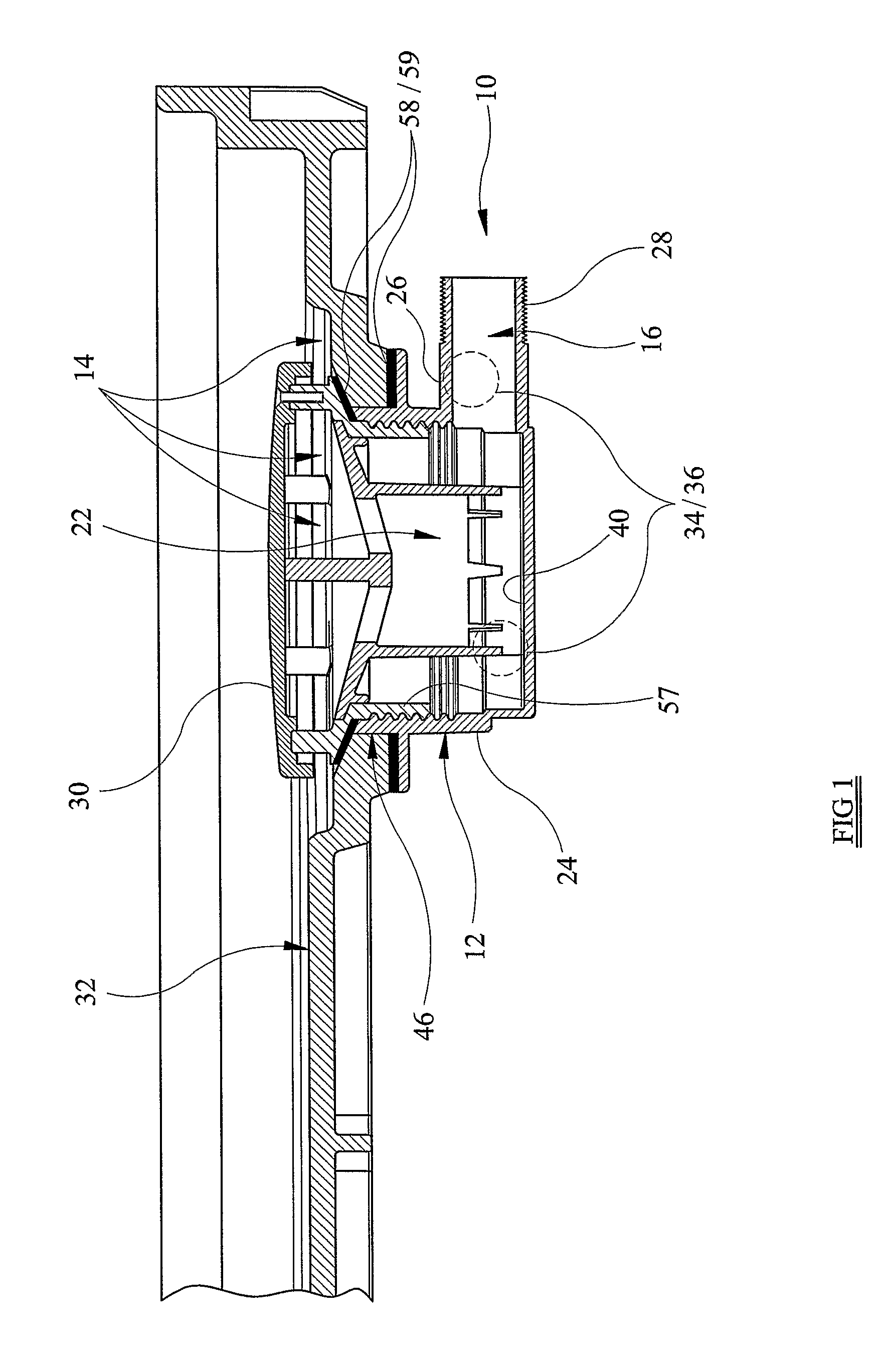
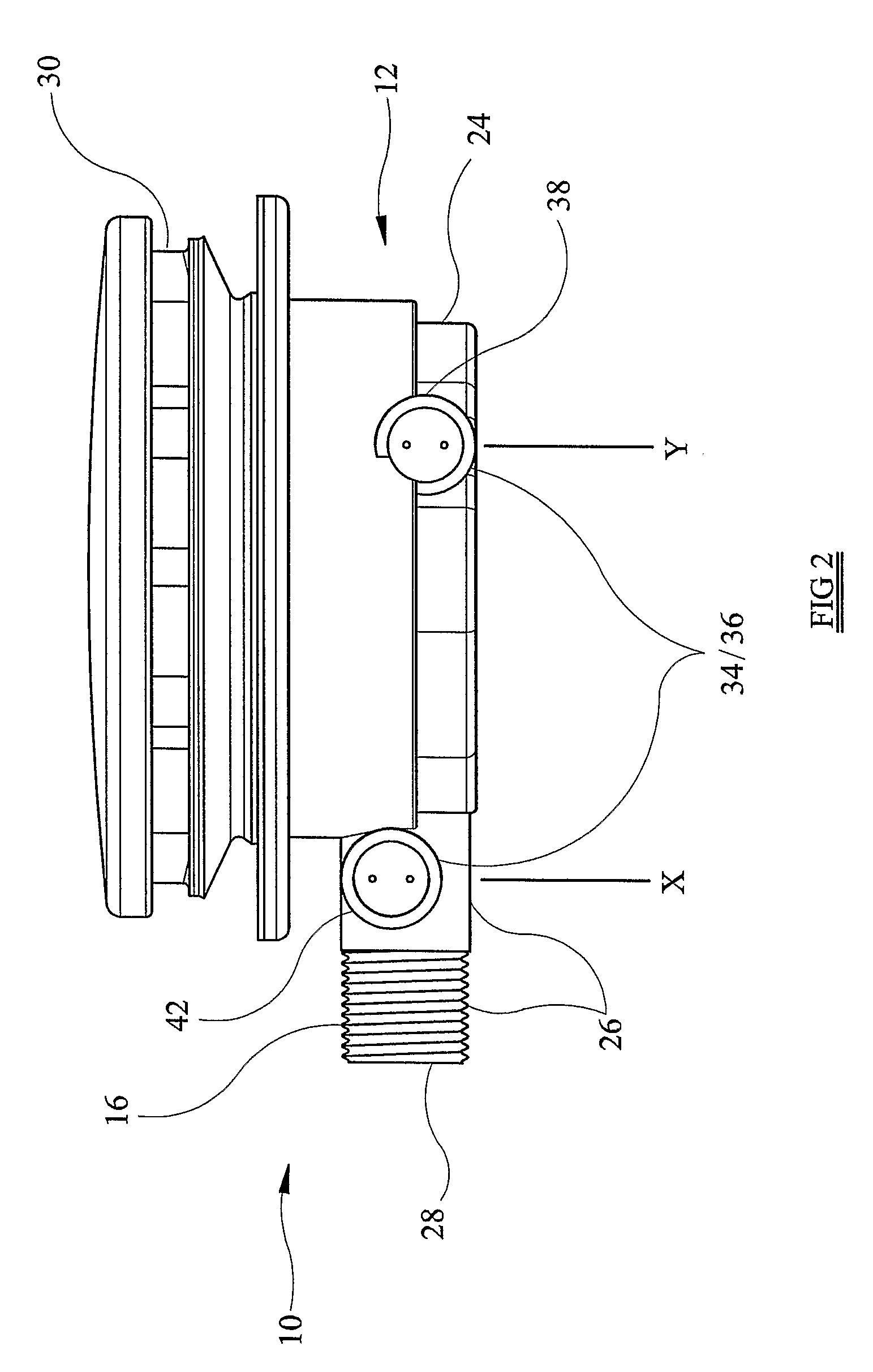
[0006]According to a first aspect of the present invention, there is provided pumped drainage apparatus for a shower, the apparatus comprising a waste water unit having a waste water inlet for accepting waste water runoff from a shower, and a waste water outlet in fluid communication with the waste water inlet; a pump in fluid communication with the waste water unit; a sensing circuit including one or more sensors for sensing waste water and isolated to prevent in use contact with the waste water; and a control circuit for controlling and varying a flow rate of the pump based on an output of the sensing circuit.

Problems solved by technology

The omission of a trap results in the possibility of undesirable odours backflowing into the shower area.
However, intrusive operational noise is a problem associated with the utilisation of a pump.

Method used


Image

  • Pumped drainage apparatus
  • Pumped drainage apparatus
  • Pumped drainage apparatus

Examples


fifth embodiment

[0052]Referring to FIG. 9, there is shown a discharge conduit 418 of pumped drainage apparatus 410. Again, like references refer to like parts. Only a single recess 444 is shown, which takes the form of a conduit of a conventional T-piece plumbing fitting. Sensor 436 is provided in a specific independent, typically injection moulded, housing 452, which is then located liquid-tightly in the recess 444. Due to the conventional T-fitting having a conventional coupling, releasably secure location of the housing 452 is simple.

[0053]Due to the housing 452, the sensor 436 remains isolated from the fluid flow in the discharge conduit 418.

[0054]Although the sensors described above are ultrasonic sensors and are isolated from the fluid flow, the sensors could project into the fluid flow, and thus be in direct contact with the fluid in the pumped drainage apparatus.

sixth embodiment

[0055]Referring toFIG. 10, there is shown a discharge conduit 518 of pumped drainage apparatus 510. Like references refer to like parts, and further detailed description is omitted.

[0056]The discharge conduit 518 is provided with two spaced conductive pipe elements 566 interconnected by coupling element 568. One end of the discharge conduit 518 fluidly communicates with waste water outlet 516 of a waste water unit, as described above, and the other end fluidly communicates with pump inlet 548.

[0057]A sensing circuit of variable flow control device 534 comprises sensors 536. In this embodiment, the sensors 536 are capacitative and are formed by the spaced conductive pipe elements 566. Each pipe element 566 is connected to circuitry of the sensing circuit via wires 570.

[0058]In this embodiment, the sensors 536 are in direct contact with the fluid flow in the discharge conduit 518. In use, the sensing circuit energises the sensors 536 which provide feedback concerning the amount of wat...


PUM


Abstract

A pumped drainage apparatus for a shower includes a waste water unit, a waste water inlet for accepting waste water runoff from a shower, a waste water outlet in fluid communication with the waste water inlet, a pump in fluid communication with the waste water unit, a sensing circuit including one or more sensors for sensing waste water, and a control circuit for controlling and varying a flow rate of the pump based on an output of the sensing circuit. The sensors may be isolated to prevent contact with waste water while the apparatus is in use. A variable flow control device for the pumped drainage apparatus is also provided.

Description

FIELD OF THE INVENTION[0001]The present invention relates to pumped drainage apparatus and, more particularly, to a variable flow control device for such apparatus.BACKGROUND OF THE INVENTION[0002]It is known to provide an electrically operated pump in fluid communication with a waste water unit of a shower for drawing waste water from the unit to a drain. The use of a pump is particularly beneficial when there is little space below the shower floor surface such as with an unbreachable solid screened floor or between joists and under floorboards to allow for a waste water unit with a trap to be fitted. The omission of a trap results in the possibility of undesirable odours backflowing into the shower area. Consequently, the pump acts to draw odours, as well as waste water, away from the shower area.[0003]The pump is also beneficial in increasing discharge flow rate where smaller diameter pipe work is used in the drainage apparatus. This helps prevent flooding in the shower area.[000...

Claims


Application Information

Patent Timeline
Patent Type & Authority Patents(United States)
IPC IPC(8): E03C1/00E03C1/22
CPCE03C1/22A47K3/28
Inventor STIMPSON, ROBERT WILLIAM
Owner DLP
Why Eureka
Try Eureka