Turbojet engine with attenuated jet noise

a jet noise and turbojet technology, applied in the direction of engines, machines/engines, engine fuctions, etc., can solve the problems of unnecessarily penalizing the performance of the aircraft and the disadvantage of generating considerable drag

Active Publication Date: 2012-01-17
AIRBUS OPERATIONS (SAS)
View PDF5 Cites 10 Cited by
  • Summary
  • Abstract
  • Description
  • Claims
  • Application Information

AI Technical Summary

Benefits of technology

[0007]The object of the present invention is to remedy this disadvantage, by generating turbulence at the boundary between said hot and cold flows only when the attenuation of the jet noise is really useful.

Problems solved by technology

These known chevrons are effective in attenuating the jet noise; however, they have the disadvantage of generating considerable drag.
Therefore, at cruising speed, the performance of the aircraft is unnecessarily penalized by said chevrons creating increased drag.

Method used


Image

  • Turbojet engine with attenuated jet noise
  • Turbojet engine with attenuated jet noise
  • Turbojet engine with attenuated jet noise

Examples


Embodiment Construction

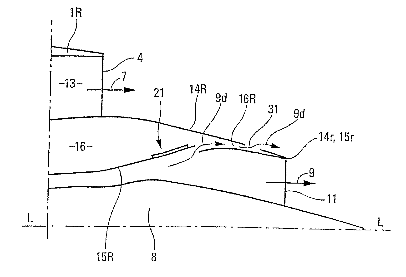
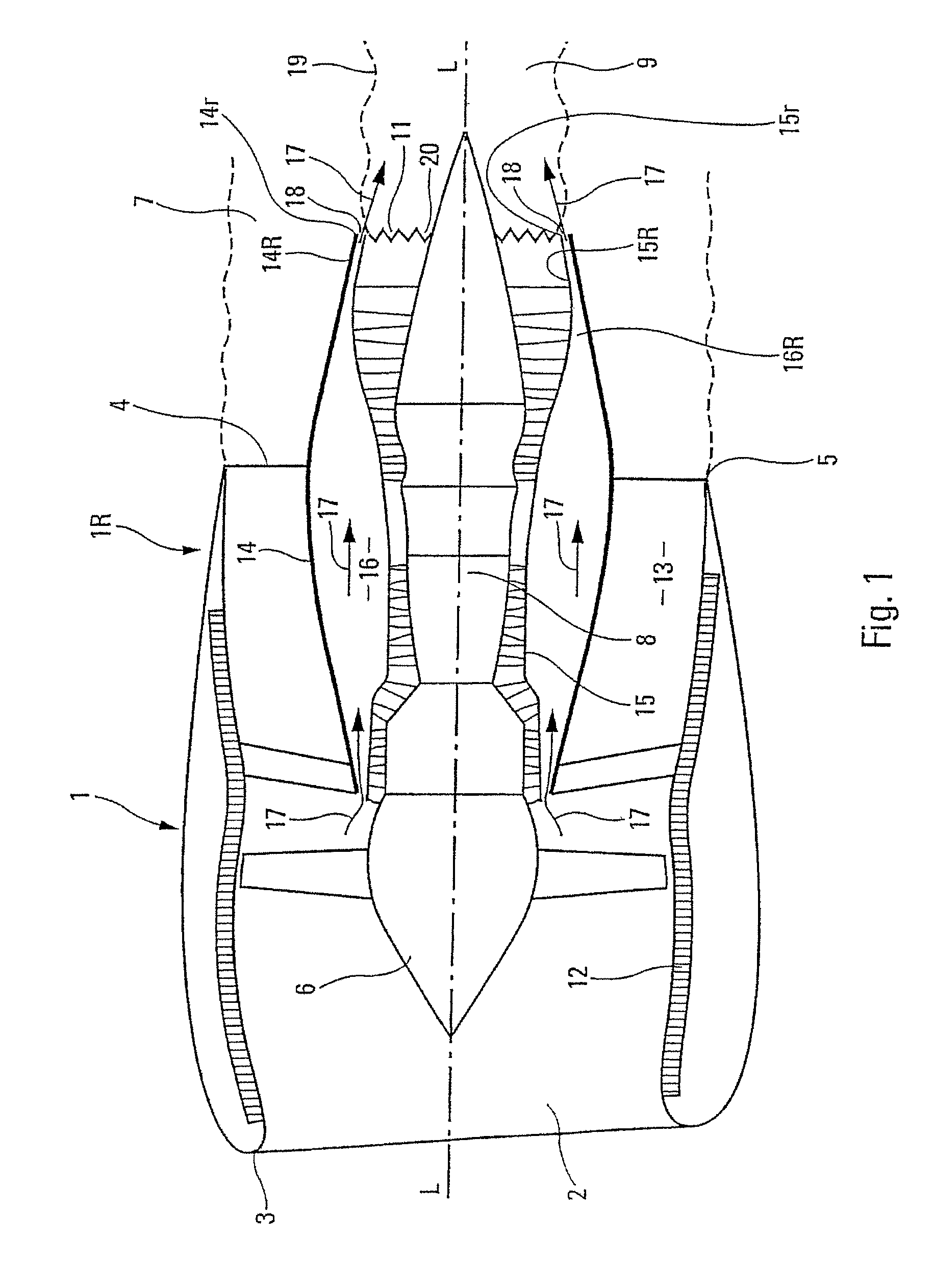
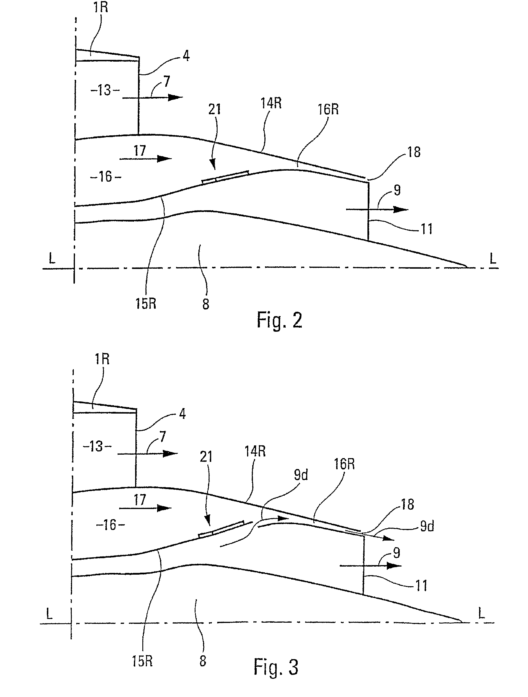
[0054]The turbofan turbine engine of a known type for an aircraft, shown in FIG. 1, comprises a hollow nacelle 1 with a longitudinal axis L-L, comprising, at the front, an air inlet 2 provided with a leading edge 3 and, in its rear portion 1R, an annular air outlet 4 provided with a trailing edge 5.

[0055]Placed axially inside said hollow nacelle 1 are:[0056]a fan 6 directed toward the air inlet 2 and capable of generating the cold flow 7 for the turbine engine;[0057]a central generator 8 comprising, in a known manner and not shown, low-pressure and high-pressure compressors, a combustion chamber and low-pressure and high-pressure turbines, said generator 8 generating the axial hot flow 9 of said turbine engine surrounded by said cold flow 7 and being enclosed in an engine cowl 15;[0058]a fan channel inner cowl 14 surrounding said hot flow generator 8; and[0059]sound attenuation coverings 12, designed to absorb the internal noises generated by the fan 6 and the hot flow generator 8.

[...


PUM


Abstract

A plurality of hatches are distributed on the rear periphery of an engine cowl. The hatches are opened only when turbojet engine power is greater than cruising power. In an open position, the hatches draw hot air jets passing through an intermediate chamber before ejecting the jets through longitudinally-distributed communication components.

Description

FIELD OF THE INVENTION[0001]The present invention relates to a turbine engine with attenuated jet noise, designed to be fitted to an aircraft.BACKGROUND OF THE RELATED ART[0002]It is known that, at the rear of a turbofan turbine engine, the cold flow and the hot flow travel in the same direction toward the downstream of said turbine engine and come into contact with one another. Since the speeds of said flows are different from each other, the result of this is fluid shear of penetration between said flows, said fluid shear generating noise, called “jet noise” in aviation technology.[0003]To attenuate such a jet noise, thought has already been given to generating turbulence at the boundary between said hot flow and said cold flow. It has therefore already been proposed to make recesses in the outlet edge of the hot flow, said recesses being distributed on the periphery of said outlet edge and each of them generally having at least the approximate shape of a triangle, whose base is i...

Claims


Application Information

Patent Timeline
Patent Type & Authority Patents(United States)
IPC IPC(8): F02K1/00F02K1/28
CPCF02K1/46F02K1/50B64D2033/024F05D2260/96
Inventor PORTE, ALAIN
Owner AIRBUS OPERATIONS (SAS)
Why Eureka
Try Eureka