
Eureka
For R&D, Eureka makes reading and utilizing patents & technical documents easy.
Eureka AIR
Designed for self-driven R&D workflows. Generate viable solutions, solve complex R&D challenges, empower your innovation with AI.

Eureka Materials
Designed for material experts only. Revolutionize your material R&D, from search, analyze, to developing new materials.

TechResearch
Generate reliable direction feasibility study reports for your R&D in just a few steps.

TechSeek
Discover and master advanced knowledge NOW. Basics, ideas, possibilities, all at once.

TechMind
As an expert in R&D Theories, TechMind can generates customized viable solutions instantly.

TechRisk
Analyze your overall solution with one click, know your potential R&D risks in advance.

TechMonitor
Get weekly tech updates, stay abreast of the latest tech innovations and key insights.
Compensation shaft of an internal combustion engine
a multi-cylinder engine and compensation shaft technology, applied in the direction of machines/engines, mechanical equipment, rotary machine parts, etc., can solve the problems of certain friction amount, and achieve the effect of reducing diameter, good strength value and functional reliability
- Summary
- Abstract
- Description
- Claims
- Application Information
AI Technical Summary
Benefits of technology
Problems solved by technology
Method used
Image

Examples
Embodiment Construction
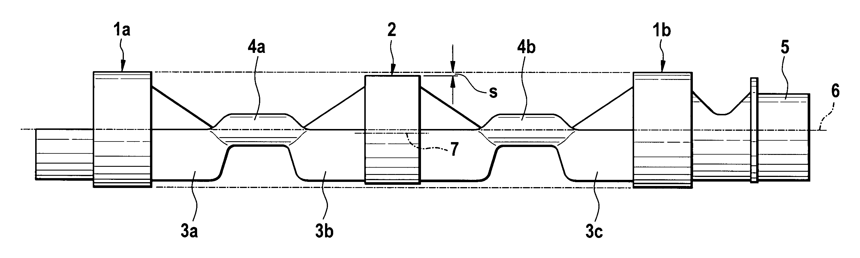
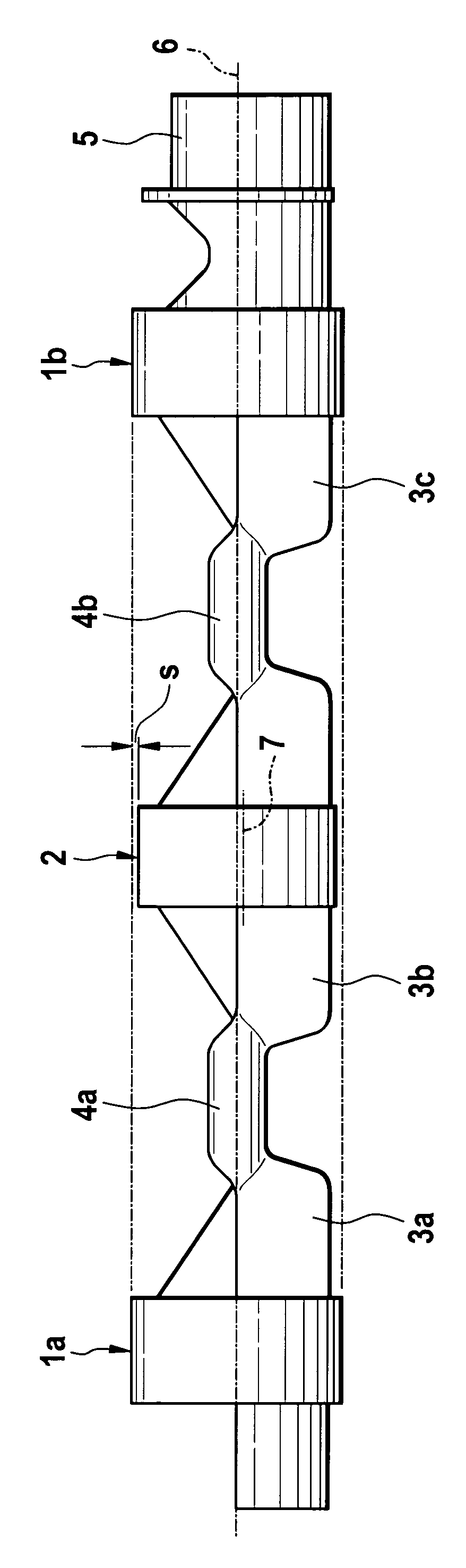
[0014]The sole FIGURE shows a compensation shaft of the present invention comprising bearing pegs 1a, 1b and 2 and unbalanced masses 3a, 3b and 3c. The unbalanced masses 3a-3c are connected to one another by flexible sections 4a and 4b, each of which has a smaller diameter and a circular cross-section. Compared to the bearing pegs 1a and 1b, the bearing peg 2 has a reduced diameter, so that, in the installed state of the compensation shaft in a crankcase, not illustrated, in an internal combustion engine, a mounting lash enhanced by the factor “s” is formed at one mounting location of the crankcase.
[0015]A central axis of the bearing peg 2 is identical to the longitudinal axis 6 of the compensation shaft. Alternatively, the invention also provides that a central axis of the bearing peg 2, identified at 7 in the FIGURE, may extend eccentrically to the longitudinal axis 7 in direction of the unbalanced masses of the compensation shaft. The eccentricity of this central axis 7 is orient...
PUM
 Abstract
Description
Claims
Application Information
 - R&D Engineer
- R&D Manager
- IP Professional
- Industry Leading Data Capabilities
- Powerful AI technology
- Patent DNA Extraction
Browse by: Latest US Patents, China's latest patents, Technical Efficacy Thesaurus, Application Domain, Technology Topic, Popular Technical Reports.
© 2024 PatSnap. All rights reserved.Legal|Privacy policy|Modern Slavery Act Transparency Statement|Sitemap|About US| Contact US: help@patsnap.com