
Eureka
For R&D, Eureka makes reading and utilizing patents & technical documents easy.
Eureka AIR
Designed for self-driven R&D workflows. Generate viable solutions, solve complex R&D challenges, empower your innovation with AI.

Eureka Materials
Designed for material experts only. Revolutionize your material R&D, from search, analyze, to developing new materials.

TechResearch
Generate reliable direction feasibility study reports for your R&D in just a few steps.

TechSeek
Discover and master advanced knowledge NOW. Basics, ideas, possibilities, all at once.

TechMind
As an expert in R&D Theories, TechMind can generates customized viable solutions instantly.

TechRisk
Analyze your overall solution with one click, know your potential R&D risks in advance.

TechMonitor
Get weekly tech updates, stay abreast of the latest tech innovations and key insights.
Clamp device and clamping system using such device
A clamping device and conical technology, applied in positioning devices, clamping, manufacturing tools, etc., can solve the problems of large size and complex structure, and achieve the effect of improving rigidity
- Summary
- Abstract
- Description
- Claims
- Application Information
AI Technical Summary
Problems solved by technology
Method used
Image

Examples
specific Embodiment approach
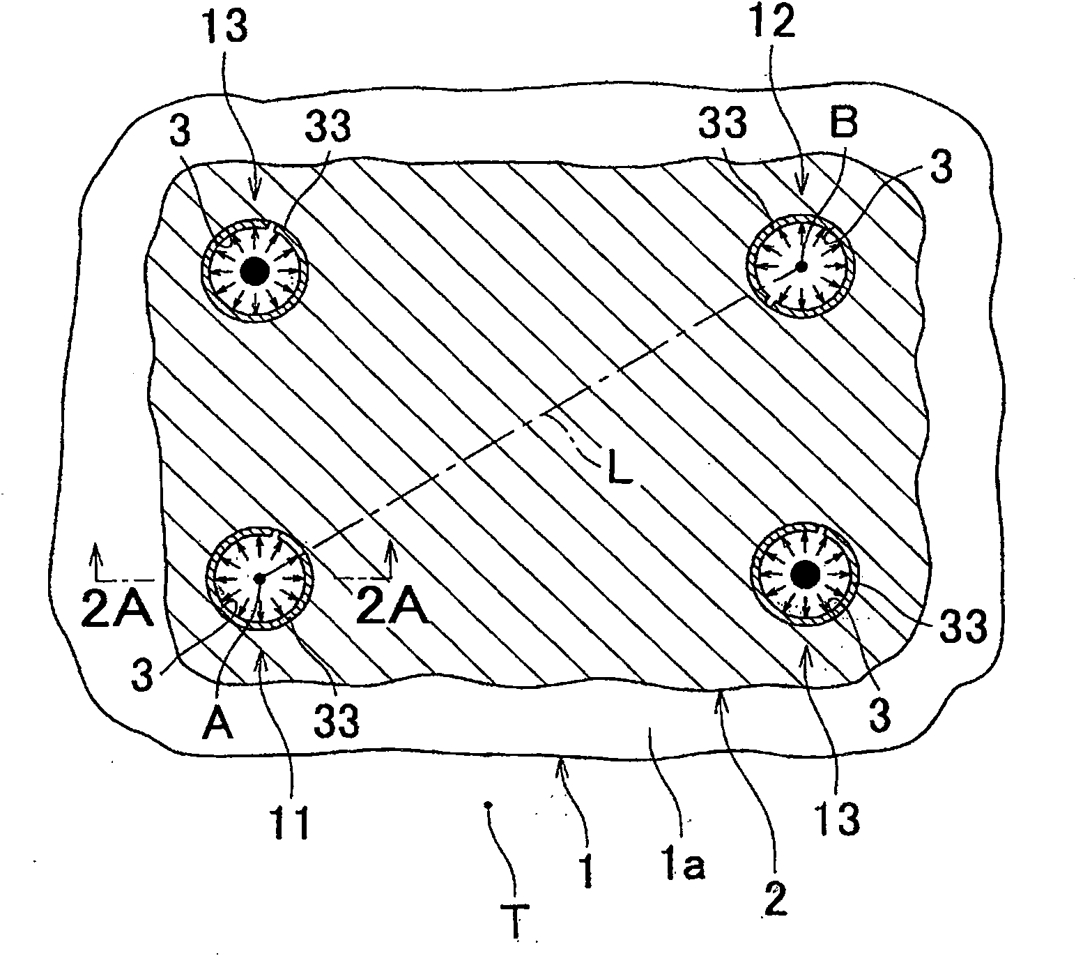
[0064] Figure 1-Figure 7B One embodiment of the present invention is shown and exemplifies the application of the clamping device of the present invention to a clamping system for a work pallet.
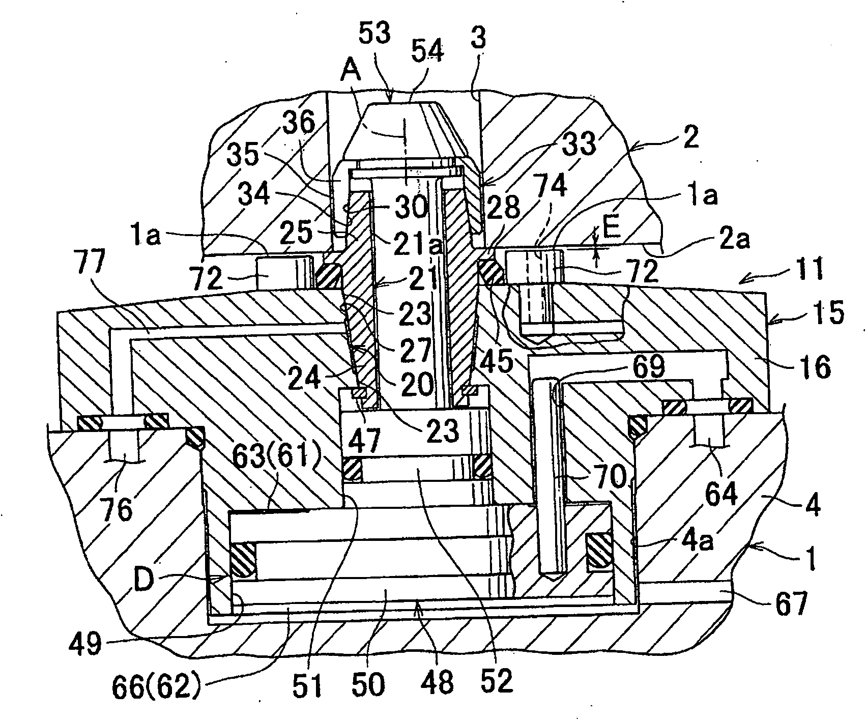
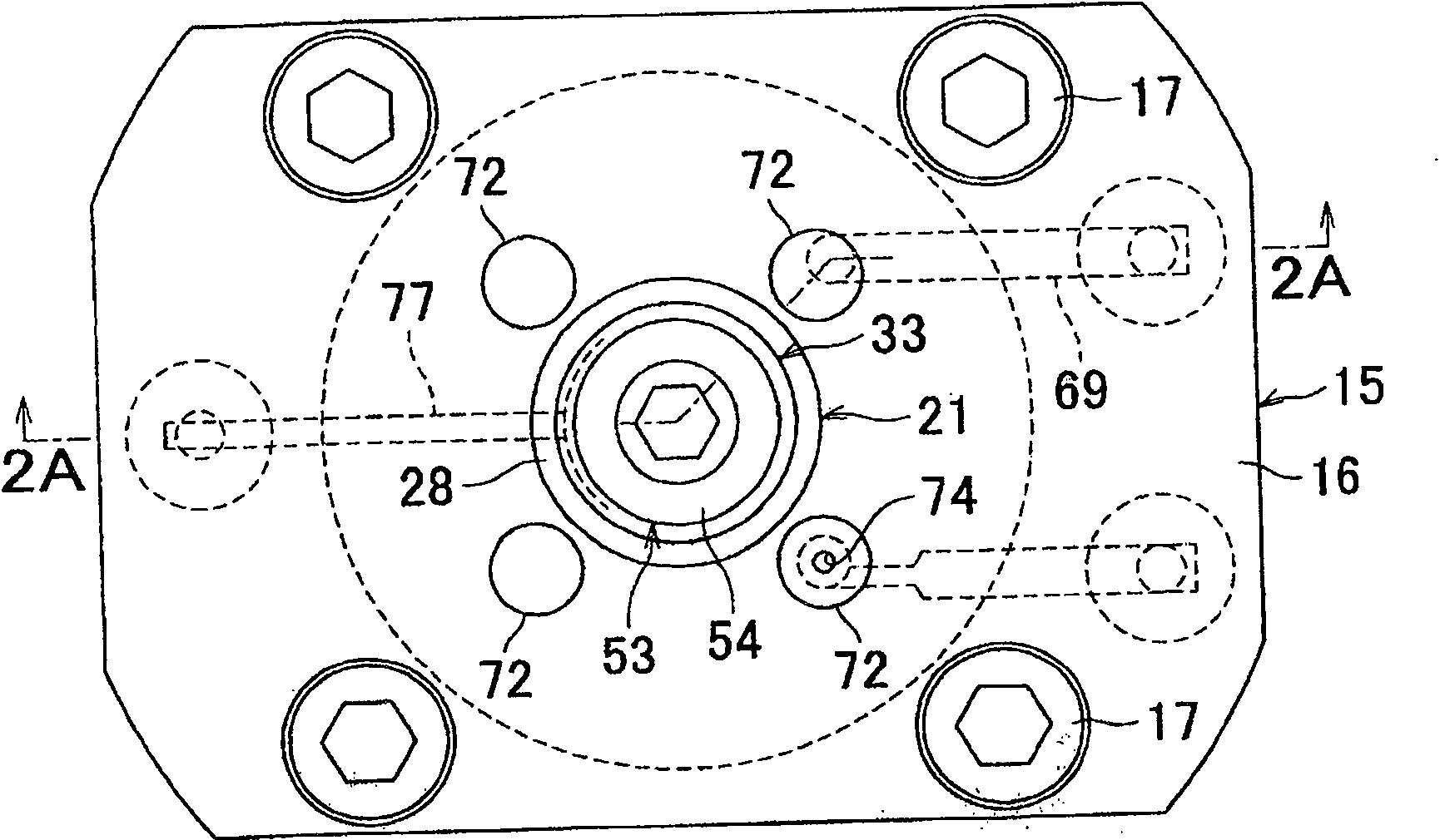
[0065] figure 1 is a cross-sectional view of the clamping system. Figure 2A is the front view of the section of the first clamping device of the clamping system, and corresponds to the figure 1 or Figure 2B View of the cross-section taken at line 2A-2A. Figure 2B is a top view of the clamping device. Figure 3A-Figure 4B is the view that explains the operation. Figure 5A-Figure 5C Exemplary variants of the first clamping device are shown. Figure 6A and Figure 6B A second clamping device of the clamping system is shown. Figure 6C and Figure 6D Exemplary variants of the second clamping device are shown in each case. Figure 7A and Figure 7B A third clamping device of the clamping system is shown.
[0066] Such as figure 1 and Figure 2A As shown, in this embo...
PUM
 Abstract
Description
Claims
Application Information
 - R&D Engineer
- R&D Manager
- IP Professional
- Industry Leading Data Capabilities
- Powerful AI technology
- Patent DNA Extraction
Browse by: Latest US Patents, China's latest patents, Technical Efficacy Thesaurus, Application Domain, Technology Topic, Popular Technical Reports.
© 2024 PatSnap. All rights reserved.Legal|Privacy policy|Modern Slavery Act Transparency Statement|Sitemap|About US| Contact US: help@patsnap.com