
Compression garment having grip

Active Publication Date: 2012-01-17
KPR U S LLC
View PDF100 Cites 25 Cited by
  • Summary
  • Abstract
  • Description
  • Claims
  • Application Information

AI Technical Summary

Benefits of technology

[0006]Another aspect of the invention is directed to a compression garment adapted for placement in a self-retaining configuration on a body part for imparting compression therapy on the body part. The compression garment includes a flexible wrap having a proximal end sized for wrapping around a proximal portion of the body part, a distal end opposite the proximal end for wrapping around a distal portion of the body part, and first and second side edges extending between the proximal end and the distal end. A bladder is held in use by the wrap for compressing the body part. The bladder has an inflatable chamber and a port in fluid communication with the chamber for selectively delivering fluid from a fluid source to the chamber to inflate the chamber to compress the body part. An inner flap extends from one of the side edges and an outer flap extending from another of the side edges. The outer flap overlaps the inner flap when the garment in use on the body part. A fastener is attached to at least one of the inner flap and the outer flap for securing the wrap in the self-retaining configuration on the body part in which the proximal end is wrapped around the proximal portion of the body part, the distal end is wrapped around the distal portion of the body part, and the outer flap overlaps the inner flap. The inner flap has a length extending from the respective side edge of the wrap to a free end and a maximum width measured generally perpendicular to a median circumferential centerline of the inner flap. The outer flap has a length extending from the respective side edge of the wrap to a free end, a maximum width measured generally perpendicular to a median circumferential centerline of the outer flap that is at least about half as wide as the maximum width of the inner flap, and a neck having a width less than the maximum width of the outer flap. The maximum width of the outer flap is positioned on the outer flap closer to the free end than the neck is positioned such that when the outer flap overlaps the inner flap at least a portion of the inner flap is not overlapped by the outer flap and is accessible adjacent the neck to facilitate gripping of the inner flap by fingers of a person to tighten the wrap about the body part.

Problems solved by technology

For example, when blood circulation in these veins is retarded due to illness, injury, or inactivity, there is a tendency for blood to accumulate or pool.
A static pool of blood may lead to the formation of a blood clot, which can interfere with cardiovascular circulation.
A pulmonary embolus can form from the fragment potentially blocking a main pulmonary artery, which may be life threatening.
The cyclical inflation of the compression garment enhances blood circulation and decreases the likelihood of DVT.
This can be very difficult when the compression garments are used during and after ambulation, such as walking, sitting, standing, and rolling over.
The garments tend to slide down the body part causing misalignment of inflatable bladders with corresponding body parts, which may result in ineffective compression therapy and / or discomfort.

Method used


Image

  • Compression garment having grip
  • Compression garment having grip
  • Compression garment having grip

Examples


Embodiment Construction

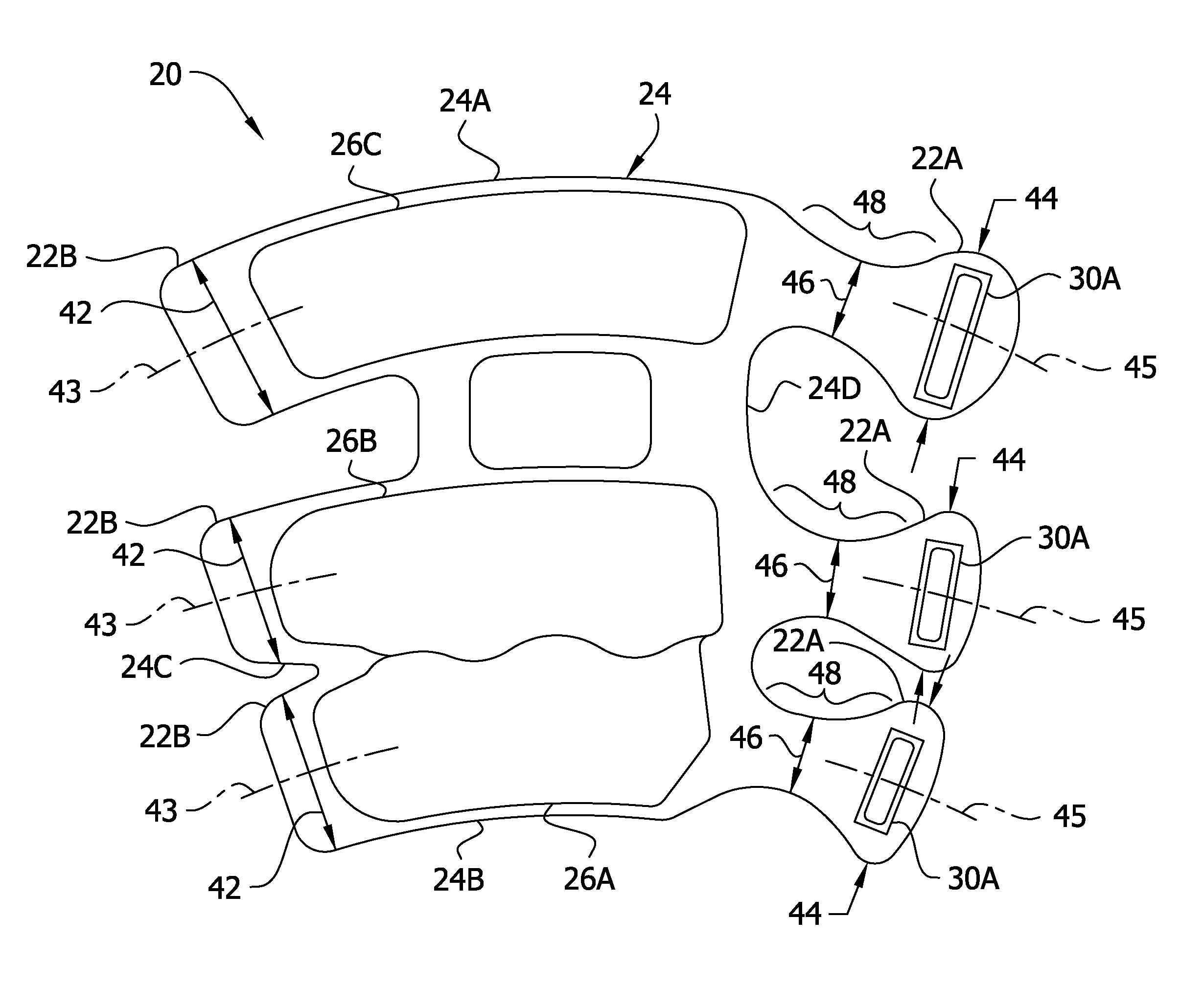
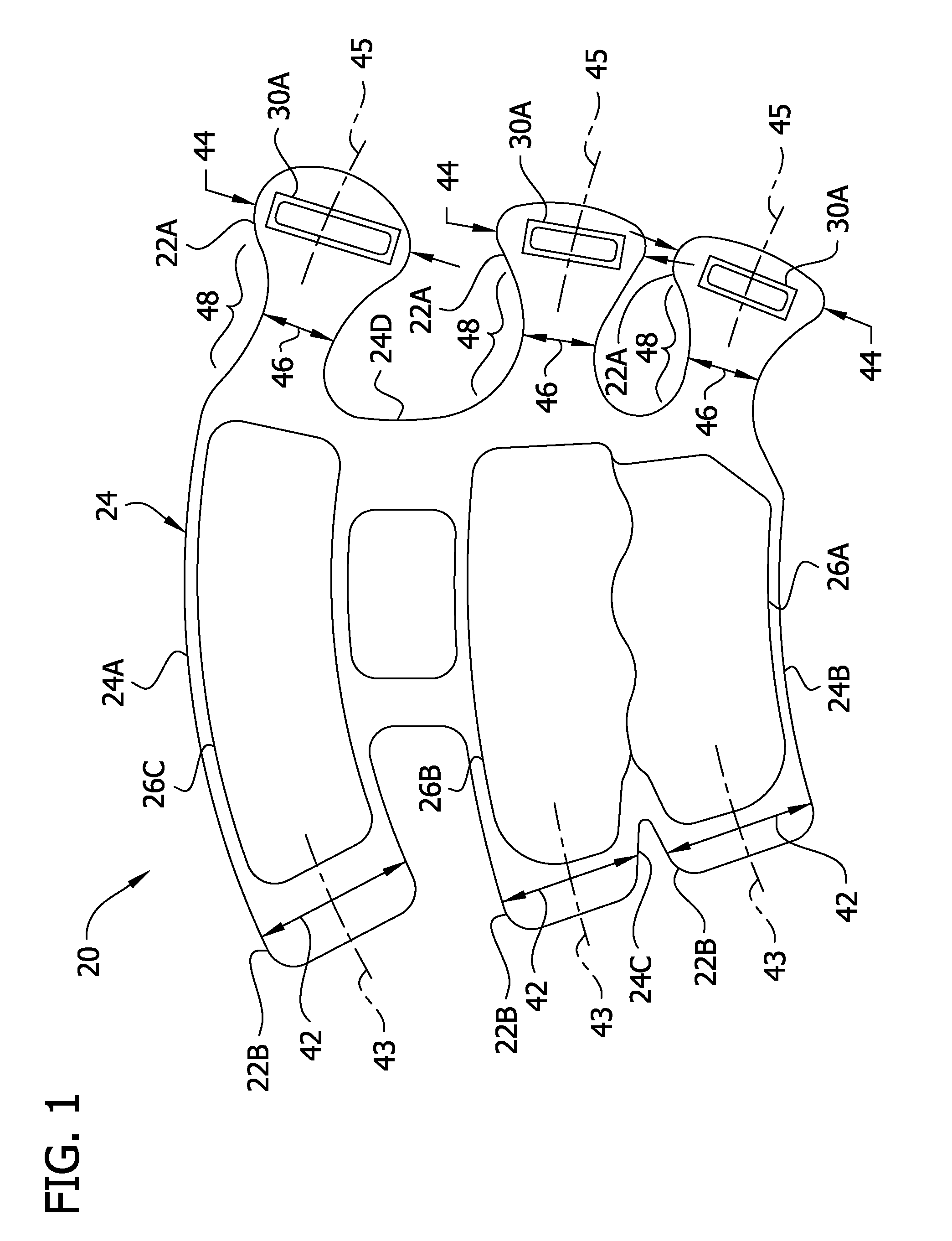
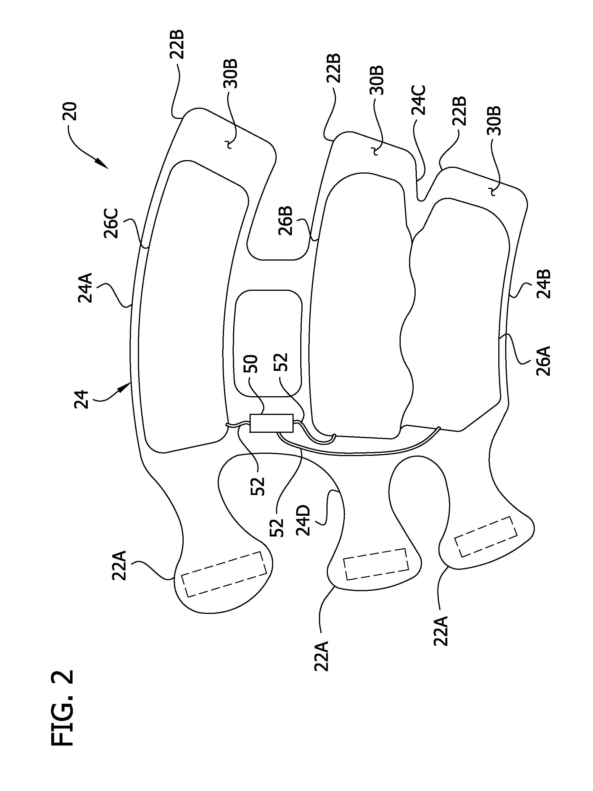
[0014]Referring to the drawings and in particular to FIGS. 1-3, a compression garment for applying compression therapy to a body part of a wearer is generally indicated by the reference number 20. The compression garment 20 is adapted for placement on the body part (e.g., a leg or arm). The illustrated compression garment 20 is adapted for placement on a leg. The compression garment 20 may be used to provide compression therapy such as constant or intermittent compression to the body part.

[0015]The compression garment 20 includes a flexible wrap, generally designated by 24, and three bladders 26A-26C. The wrap 24 is configured for holding the bladders 26A-26C for compressing the leg while the wrap is in a self-retaining configuration on the leg (e.g., FIG. 3). The wrap 24 has a proximal end 24A sized for wrapping around a proximal portion of the leg, a distal end 24B opposite the proximal end for wrapping around a distal portion of the leg, and lateral side edges 24C, 24D extending ...


PUM


Abstract

A compression garment adapted for placement in a self-retaining configuration on a body part for imparting compression therapy on the body part. The compression garment includes a flexible wrap and a bladder held in use by the wrap for compressing the body part. The wrap includes and inner flap and an outer flap. The outer flap overlaps the inner flap when the garment is in a self-retaining configuration on the body part. A fastener secures the wrap in the self-retaining configuration. When the outer flap overlaps the inner flap, at least a portion of the inner flap is exposed forming a grip for grasping the inner flap when tightening and fastening the garment in the self-retaining configuration.

Description

FIELD OF THE INVENTION[0001]The present invention generally relates to a compression garment, and more particularly to a compression garment having a grip for facilitating application of the garment to a body part.BACKGROUND OF THE INVENTION[0002]A major concern for generally immobile patients and like persons are medical conditions that form blood clots, such as, deep vein thrombosis (DVT) and peripheral edema. Such patients and persons include those undergoing surgery, anesthesia, extended periods of bed rest, etc. These blood clotting conditions generally occur in the deep veins of the lower extremities and / or pelvis. These veins, such as the iliac, femoral, popliteal, and tibial return deoxygenated blood to the heart. For example, when blood circulation in these veins is retarded due to illness, injury, or inactivity, there is a tendency for blood to accumulate or pool. A static pool of blood may lead to the formation of a blood clot, which can interfere with cardiovascular circ...

Claims


Application Information

Patent Timeline
IPC IPC(8): A61F5/00
CPCA61F13/085
Inventor BRUEHWILER, MICHELROSEN, MELISSADESHPANDE, MANISH
Owner KPR U S LLC
Learn More