Centre arm for holding an upper contact grilling or roasting plate as well as contact grilling or roasting devices with such a centre arm

a centre arm technology, which is applied in the field of centre arms for holding an upper contact grilling or roasting plate, can solve the problems of difficult cleaning of the centre arm element from the outside, increased risk of soiling inside the centre arm element, and laborious construction, so as to achieve precise and easy adjustment of weight relief

Active Publication Date: 2012-01-24
H H SCHOLZ
View PDF26 Cites 8 Cited by
  • Summary
  • Abstract
  • Description
  • Claims
  • Application Information

AI Technical Summary

Benefits of technology

[0006]It is therefore the object of the present invention to provide a centre arm with a device for weight relief, which is improved from hygienic aspects and which ensures precise and easy adjustment of weight relief. Furthermore it is the object of the invention to propose a corresponding contact grilling device.
[0007]This object is achieved by a centre arm of the kind mentioned herein-before by the fact that the adjusting device includes a control profile element which has a control profile for bringing about an axial movement of the sliding element in the longitudinal direction of the guide means. With this design according to the invention, on the one hand displacement of the actuating element from the upper side to the end face of the centre arm results in creating a closed upper side of the centre arm, so that penetration of fat, vapours or the like is prevented and easy cleaning is ensured. On the other hand, the control profile element which is referred to as an adjusting crown or crown guide allows reliable and easy adjustment.
[0008]An appropriate development is distinguished by the fact that the control profile element is a stepped element having at least two latch steps, the latch steps being axially offset from each other in the longitudinal direction of the guide means. To put it another way, the stepped element has at least two adjusting positions which, starting from the actuating element, are radially offset and located one behind the other. With the design according to the invention, firstly a reduction of the adjusting positions actually needed and secondly neat separation of the essential adjusting positions can be achieved. As a result the reliability and the handling are simplified.
[0009]Advantageously, the guide means includes two guide rods, so that the sliding element is guided on two guide rods. Hence the functionality and reliability of the device for weight relief is improved in particular with respect to handling.
[0010]A particularly preferred embodiment is characterised in that the centre arm according to any one of claims 1 to 13 is provided with an upper contact grilling or roasting plate. With this combination an independent grilling or roasting device is provided, which is simple to clean and easy to handle.

Problems solved by technology

The construction of the adjusting device known from the state of the art, which is oriented transversely to the longitudinal axis of the guide means, firstly however has the drawback that it is elaborate in construction.
Secondly, for the actuating element or bearing bush as part of the adjusting device an aperture is necessary, namely an opening with a hole circle, on the upper side of the centre arm element, which on the one hand increases the risk of soiling inside the centre arm element and on the other hand makes the process of cleaning the centre arm element from the outside difficult.
To put it another way, the known device for weight relief is inadequate from hygienic aspects.
Also, handling of the actuating element for adjustment of weight relief is laborious and imprecise and allows only a short adjusting path.

Method used


Image

  • Centre arm for holding an upper contact grilling or roasting plate as well as contact grilling or roasting devices with such a centre arm
  • Centre arm for holding an upper contact grilling or roasting plate as well as contact grilling or roasting devices with such a centre arm
  • Centre arm for holding an upper contact grilling or roasting plate as well as contact grilling or roasting devices with such a centre arm

Examples


Embodiment Construction

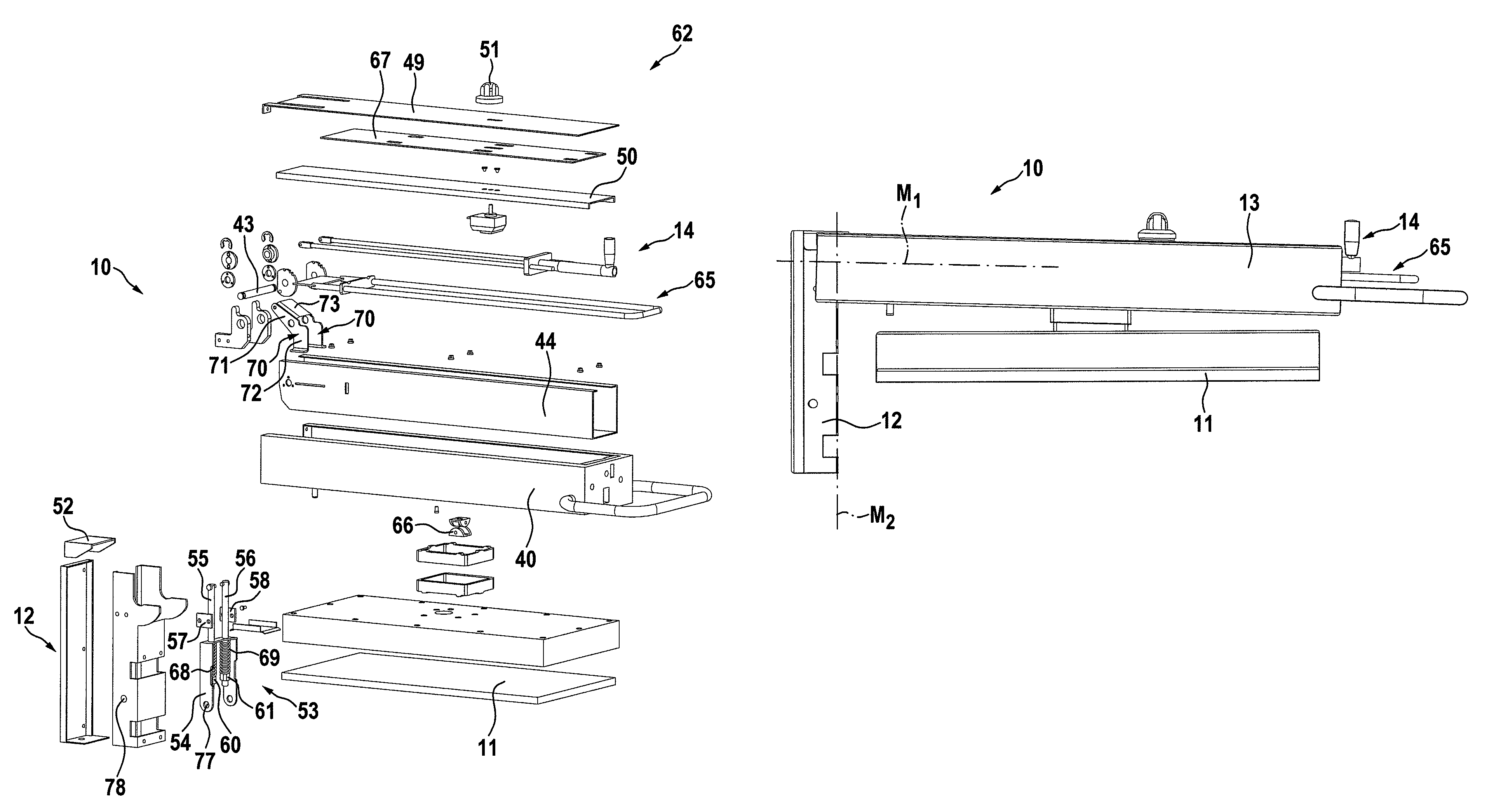
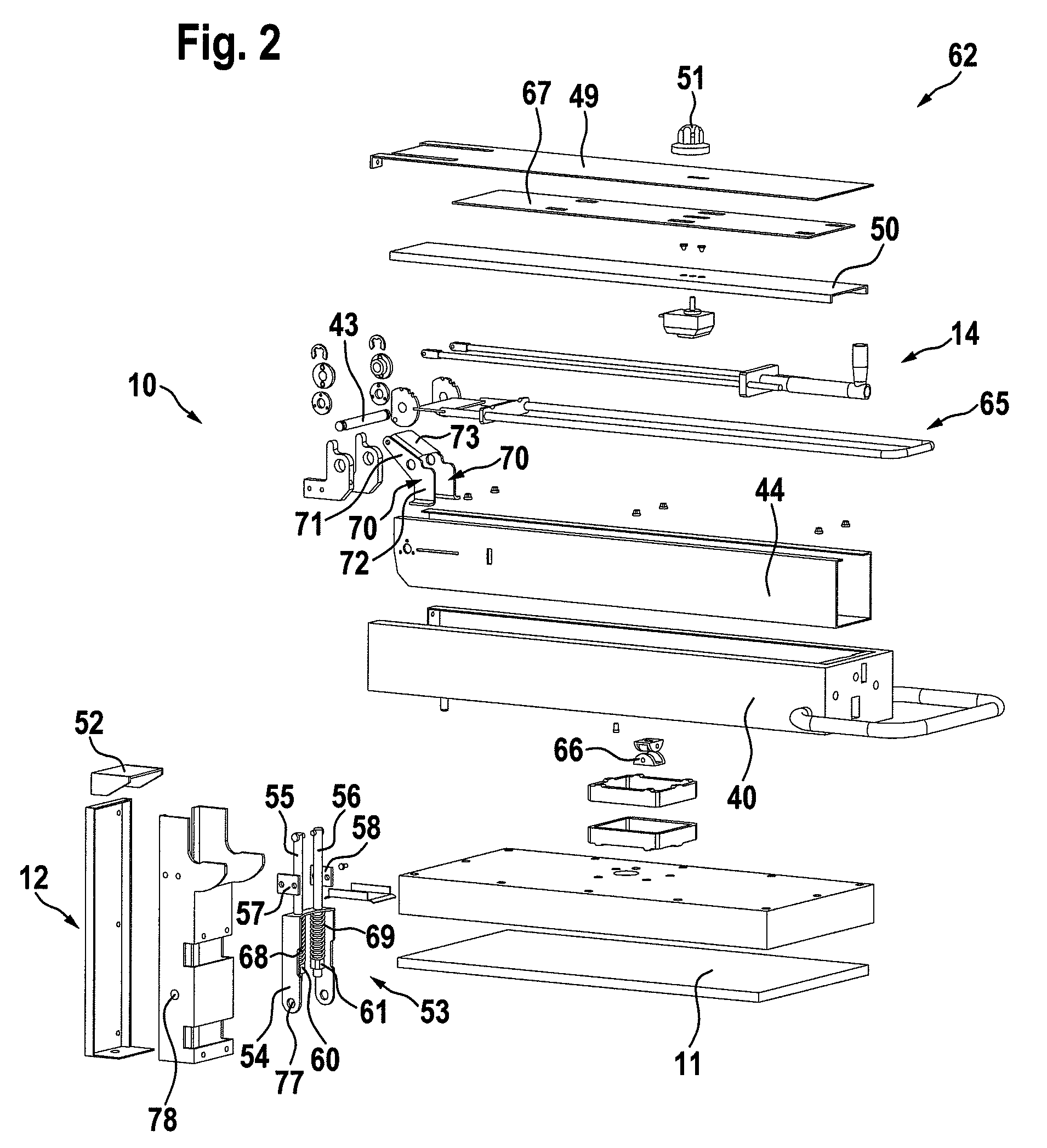
[0021]The centre arm shown in the figures serves as a conversion kit or, in combination with an upper contact grilling or roasting plate, as an independent grilling or roasting device, and can be used on its own or in combination with a lower contact grilling or roasting plate to form a contact grilling or roasting device.

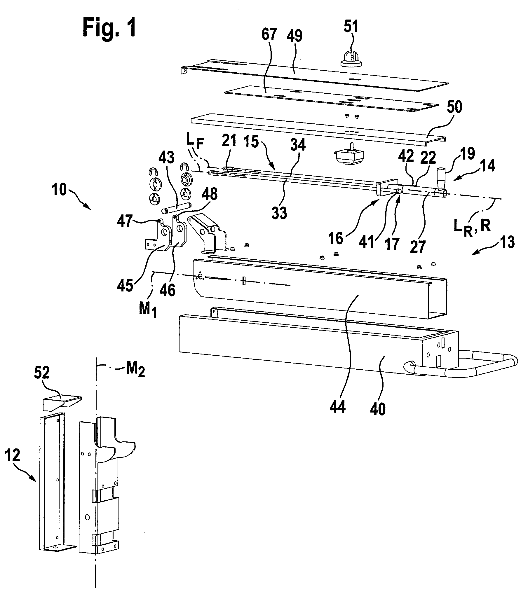
[0022]FIG. 1 shows an exploded view of a centre arm 10 which is constructed and designed to receive an upper contact grilling or roasting plate 11. The centre arm 10 essentially consists of a vertical supporting section 12 and a holding section 13 arranged pivotably on the supporting section 12. The term “vertical supporting section 12” means that the supporting section 12 is oriented perpendicularly to a plane E usually spanned by a table, a base or the like, expressly also including an orientation which is slightly inclined from the perpendicular. The upper contact grilling or roasting plate 11 is attached to the holding section 13. Associated with the holding se...


PUM


Abstract

The invention concerns a centre arm for holding an upper contact grilling or roasting plate, the centre arm having a substantially vertical supporting section and a holding section which is arranged pivotably on the vertical supporting section and to which is attached the contact grilling or roasting plate, and in the holding section being arranged a device for weight relief for the upper contact grilling or roasting plate to be fitted on the holding section, the device for weight relief including at least one guide means which is constructed and designed at one end for pivotable mounting and on which is movably arranged a sliding element, a return element arranged on the free end of the guide means and secured by a stop means between the sliding element and the stop means, and also an adjusting device which can be actuated by means of an actuating element for varying the distance between the sliding element and the stop means in the longitudinal direction of the guide means, which is distinguished in that the adjusting device includes a control profile element which has a control profile for bringing about an axial movement of the sliding element in the longitudinal direction of the guide means. Furthermore the invention concerns a contact grilling or roasting device having such a centre arm.

Description

CROSS-REFERENCE TO RELATED APPLICATIONS[0001]This application claims the priority of German patent application DE 10 2008 056 475.3, filed on Nov. 5, 2008, the subject matter of which is incorporated herein by reference.BACKGROUND OF THE INVENTION[0002]The invention concerns a centre arm for holding an upper contact grilling or roasting plate, wherein the centre arm has a substantially vertical supporting section and a holding section which is arranged pivotably on the vertical supporting section and to which the upper contact grilling or roasting plate can be attached, and in the holding section is arranged a device for weight relief for the upper contact grilling or roasting plate to be fitted on the holding section, the device for weight relief including at least one guide means which is constructed and designed at one end for pivotable mounting and on which is movably arranged a sliding element, a return element arranged on the free end of the guide means and secured by a stop m...

Claims


Application Information

Patent Timeline
Patent Type & Authority Patents(United States)
IPC IPC(8): A47J37/06
CPCA47J37/0611
Inventor SCHOLZ, KAYLANGGUTH, OTTOANKLAM, KARSTEN
Owner H H SCHOLZ
Why Eureka
Try Eureka