Method and system for performing adaptive image acquisition

a technology of image acquisition and adaptive image, applied in the field of image acquisition system, can solve the problems of not being able to solve the problem of a viable solution, requiring too many uavs and operators to cover even a limited coverage area, and a delay in the target revisit period, so as to achieve lower resolution images and high resolution images

Active Publication Date: 2012-01-24
SRI INTERNATIONAL
View PDF3 Cites 44 Cited by
  • Summary
  • Abstract
  • Description
  • Claims
  • Application Information

AI Technical Summary

Problems solved by technology

To achieve persistent surveillance using UAVs with current technology requires too many UAVs and operators to cover even a limited coverage area.
Obviously, this is not a viable solution.
Such re-scanning causes a delayed target revisit period, e.g., as much as 20 minutes.
Direct-operator-control of imaging sensors, such as cameras, significantly limits the capabilities of an imaging system.
For example, even if a camera can take 30 pictures of 30 different places in one second, the camera operator can not understand them, let alone control a camera to take 30 pictures of 30 different places.
Because of these limitations, current UAVs monitor large areas but with very low update rates for regions that they are not being immediately imaged, and for the targets that are being imaged, the update rate is typically much too high (30-60 times a second).
Almost all of the information is redundant and adds little or no intelligence value.
Additionally, intelligence opportunities often occur in a bursty manner.
This can cause a significant decrease in operators' attention and thereby increase the chance of missed targets and events.
Searching, exploiting and navigating through the vast amount of data by analysts are both inefficient and error-prone.
It will also increase the response time and cause unnecessary delay.
In addition, the total video bandwidth to cover the entire region simultaneously would be prohibitive.
This would overwhelm any available communications link.
To achieve wide area persistent surveillance, motion-imagery acquisition systems operate under severe constraints: limited bandwidth for communication, continuous operation over long periods, and unpredictable changes of tasks and environment.
In addition, intelligence has to be extracted from the huge amount of data acquired by a persistent surveillance system with low latency.

Method used


Image

  • Method and system for performing adaptive image acquisition
  • Method and system for performing adaptive image acquisition
  • Method and system for performing adaptive image acquisition

Examples


Embodiment Construction

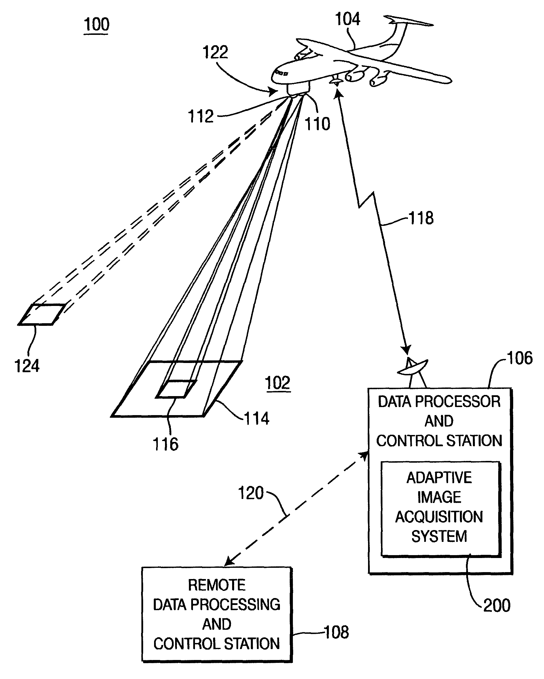
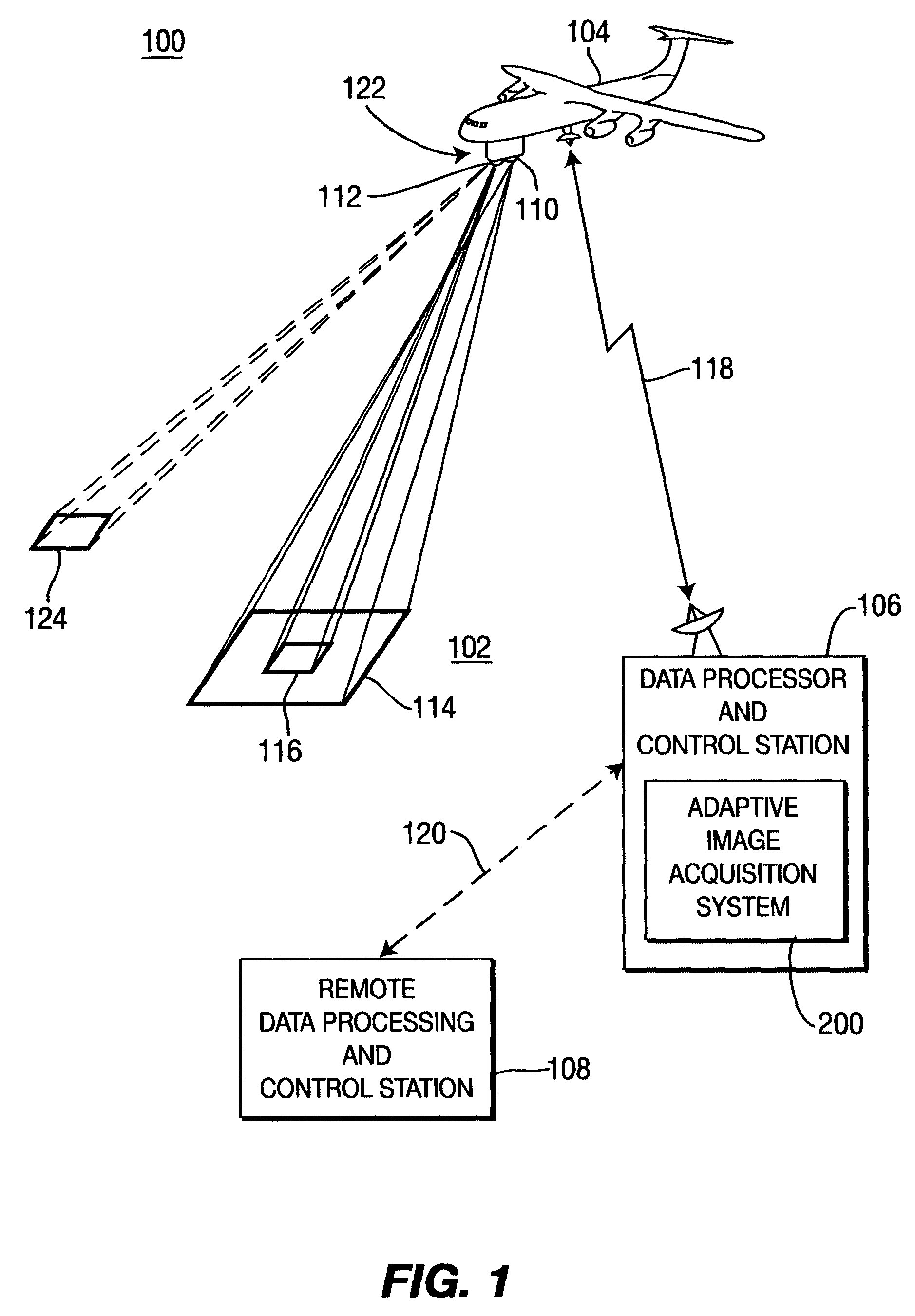
[0030]To achieve persistent surveillance using an unmanned aerial vehicle (UAV), the following three capabilities are necessary: 1) sensor systems must be operated to their maximum information collection efficiency, 2) a single operator must be able to control or guide multiple collection platforms, and 3) analysts must be able to extract in real-time or near real-time the information needed for their task, without the burden of controlling the sensor payload or the burden of searching through vast amounts of irrelevant data.

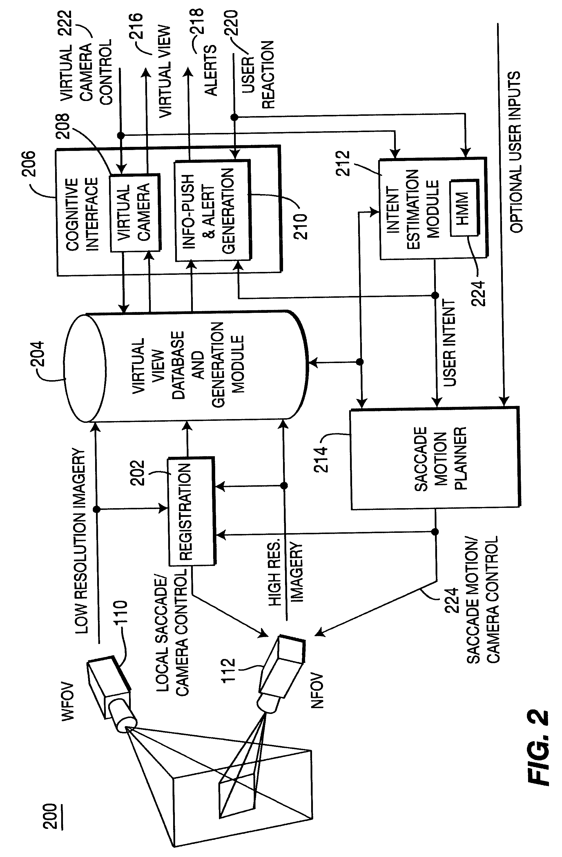
[0031]The present invention significantly improves the overall surveillance capabilities of UAVs by allowing the UAV to operate to its maximum collection capability by replacing direct control of the UAV by an operator and, instead, giving the operator indirect control. The technique is referred to as SaccadeCam—it is biologically inspired by the Saccade behavior of the human visual system of very high speed and frequent changes in the visual fixation point.

[003...


PUM


Abstract

An adaptive image acquisition system and method that generates virtual view of a surveillance scene to a user (operator), in which, the user operates the system. Through viewing the virtual view, the user controls sensors that create the virtual view. The sensors comprise at least one first sensor having a higher resolution than at least one second sensor. Images from the second sensor are processed to create an image mosaic that is overlaid with images from the higher resolution first sensor. In one embodiment of the invention, the first sensor is moved using Saccade motion. In another embodiment of the invention, a user's intent is used to control the Saccade motion.

Description

CROSS-REFERENCE TO RELATED APPLICATIONS[0001]This application claims benefit of U.S. provisional patent application Ser. No. 60 / 600,277, filed Aug. 10, 2004, and 60 / 600,278, filed Aug. 10, 2004, which are both herein incorporated by reference.GOVERNMENT RIGHTS IN THIS INVENTION[0002]This invention was made with U.S. government support under contract numbers HM1582-04-P-001 and HM1582-04-C-0010. The U.S. government has certain rights in this invention.BACKGROUND OF THE INVENTION[0003]1. Field of the Invention[0004]Embodiments of the present invention generally relate to image acquisition system and, more particularly, to adaptive image acquisition systems.[0005]2. Description of the Related Art[0006]Unmanned aerial vehicles (UAVs) are widely used as platforms for surveillance in battlefield and other environments. Generally, a UAV carries a camera and other sensor payloads and relays data collected by the sensor payloads through a radio link to an operator. The operator controls the ...

Claims


Application Information

Patent Timeline
Patent Type & Authority Patents(United States)
IPC IPC(8): H04N7/18G06V20/13
CPCG06K9/0063G06T1/0007G06T7/0028G08B13/19643G08B13/1965H04N5/2224H04N5/232H04N7/185G06K2009/2045G06T2200/32G06T2207/20228G06T2207/30181G06T7/33G06V20/13G06V10/16
Inventor CHENG, HUI
Owner SRI INTERNATIONAL
Why Eureka
Try Eureka