Parking brake control device

a technology for controlling devices and brakes, applied in braking systems, instruments, analogue processes for specific applications, etc., can solve problems such as similar problems in epbs of this type, and problems also occur

Active Publication Date: 2012-01-24
ADVICS CO LTD
View PDF19 Cites 7 Cited by
  • Summary
  • Abstract
  • Description
  • Claims
  • Application Information

AI Technical Summary

Benefits of technology

[0008]It is therefore an object of the present invention to provide a parking brake control device used in a situation where an EPB and a service brake commonly use an actuator, wherein the parking brake control device makes it possible to prevent a release control from terminating when negative influence of the service brake causes the brake force of the EPB to remain. In other words, it is an object of the present invention to prevent a residual brake force from remaining.
[0011]Thus, when the release control is executed while the service brake is operating, the parking brake control device continues the release control until the first predetermined time passes even if the pressing force for moving the friction material becomes the target value, wherein the first predetermined time is longer than a time period which it is supposed to take until the negative influence of the service brake vanishes. Therefore, it is possible to prevent the residual brake force, wherein the residual brake force is a fraction of the brake force caused by the EPB and remains after the release control.
[0017]In this case, it is possible to prevent the release control from terminating based on the first predetermined time even if the service brake is released in the middle of the release control, since the first predetermined time is set when the release control is executed while the service brake is operating.

Problems solved by technology

The EPB of this type also has a problem similar to that of the EPB using the brake cable.
By executing this type of control, the problem occurs which is similar to one described for the EPB using the brake cable.
In this case, the problem also occurs which is similar to one described for the EPB using the brake cable.

Method used


Image

  • Parking brake control device
  • Parking brake control device
  • Parking brake control device

Examples


first embodiment

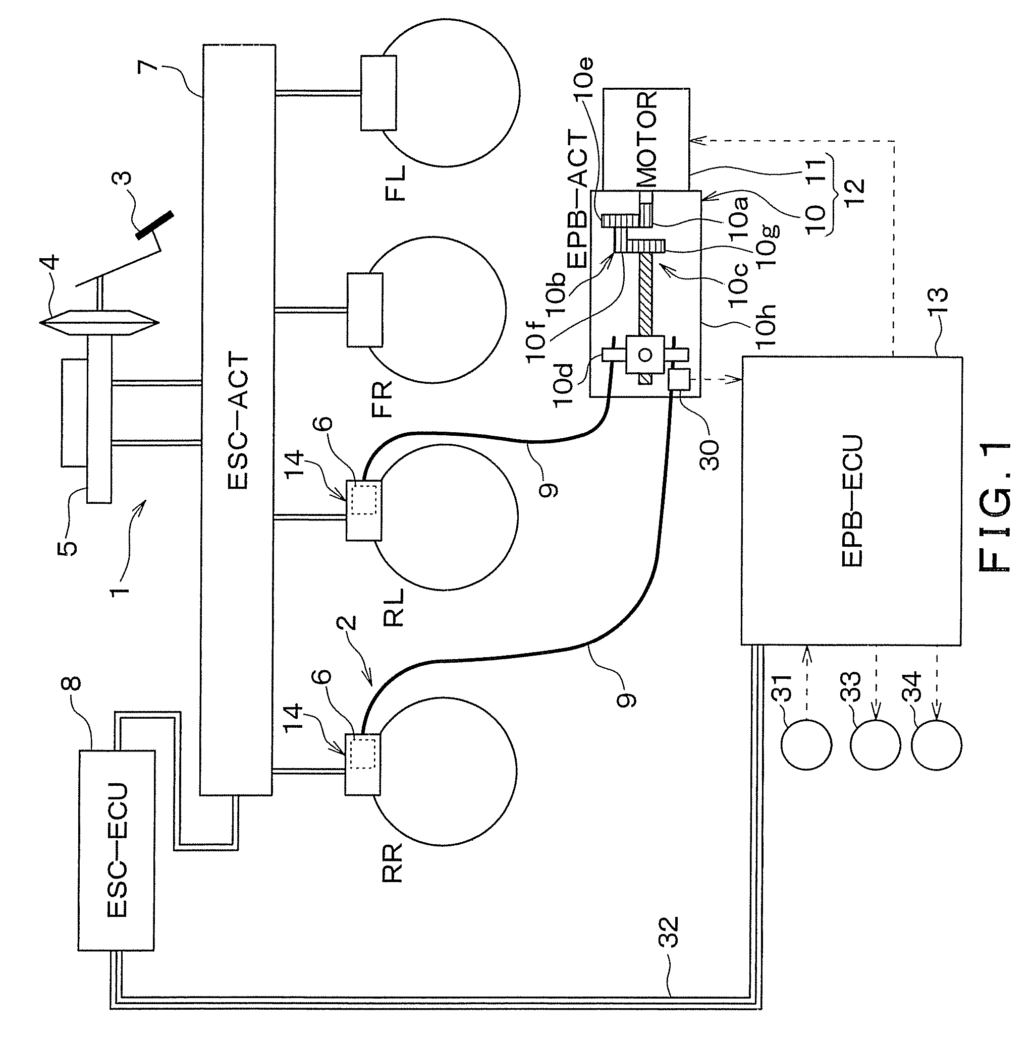
[0035]Hereinafter, a first embodiment is described. FIG. 1 is a schematic figure showing an overall structure of a vehicular brake system including a parking brake control device according to the present embodiment.

[0036]As shown in FIG. 1, the brake system includes a service brake 1 and an EPB 2. The service brake 1 generates a brake force based on a pedaling force of a driver (i.e., a force applied to a brake pedal by a driver's foot). The EPB 2 is for restricting movement of a vehicle while the vehicle is parked.

[0037]In the service brake 1, a brake booster 4 boosts the pedaling force caused by pedaling action of the driver. The service brake 1 generates a brake fluid pressure in a master cylinder 5 based on the boosted pedaling force and transmits the brake fluid pressure to a wheel cylinder (hereinafter referred to as W / C) 6 for each of wheels of the vehicle in order to generate a braking force. An actuator 7 for controlling brake fluid pressure is installed between the master ...


PUM


Abstract

When a release control is executed while a service brake is operating, a parking brake control device continues the release control until a first predetermined time passes even if the pressing force for moving a friction material becomes a target value, wherein the first predetermined time is a time period which is longer than a time period which it is supposed to take until the negative influence of the service brake vanishes.

Description

CROSS REFERENCE TO RELATED APPLICATION[0001]This application is based on and incorporates herein by reference Japanese patent applications No. 2008-031714 filed on Feb. 13, 2008.FIELD OF THE INVENTION[0002]The present invention relates to a parking brake control device for executing a lock / release control of an electric parking brake (hereinafter referred to as EPB).BACKGROUND OF THE INVENTION[0003]Conventionally, a parking brake is used for restricting movement of a parked vehicle. For example, a manual parking brake is used in which an operation force applied to an operation lever is transmitted to a brake mechanism of the parking brake when the operation lever pulls a brake cable caused by the operation force. An electrically driven parking brake is also used in which a rotational force of a motor is transmitted to the brake mechanism of the parking brake.[0004]In the electrically driven parking brake (i.e. EPB), a brake force is generated when, for example, a rotational force of...

Claims


Application Information

Patent Timeline
Patent Type & Authority Patents(United States)
IPC IPC(8): B60T7/02B60T7/12B60T8/00B60T13/74B60T17/22F16D65/14F16D65/18
CPCB60T11/046B60T13/746F16D65/18F16D65/567F16D2121/02F16D2121/14F16D2123/00F16D2125/36
Inventor KONDO, KAZUMAWATANABE, TAKASHININOYU, MASAKI
Owner ADVICS CO LTD
Why Eureka
Try Eureka