Eureka AIR delivers breakthrough ideas for toughest innovation challenges, trusted by R&D personnel around the world.

Graphical user interface, display control device, display method, and program

a display control device and user interface technology, applied in static indicating devices, instruments, substation equipment, etc., can solve problems such as devices not showing to users a relationship

Active Publication Date: 2012-01-24
SONY CORP
View PDF8 Cites 31 Cited by
  • Summary
  • Abstract
  • Description
  • Claims
  • Application Information

AI Technical Summary

Benefits of technology

[0009]The device described above provides an advantage in that it makes it possible to see transmitted and received e-mails at a glance based on information on the correspondent. However, the device does not show to the user a relationship between the e-mail function and another function. Therefore, when the user wants to extract a desired photograph based on e-mail time information, for example, the user searches for the desired photograph by first storing or making a note of the e-mail time information, then compare the e-mail time information to time information that is displayed on a photography application screen. Accordingly, a display method is required that is capable of defining the time information as key information and comparing a plurality of types of data to the key information. A graphical user interface is also required to implement the display method.

Problems solved by technology

However, the device does not show to the user a relationship between the e-mail function and another function.

Method used


Image

  • Graphical user interface, display control device, display method, and program
  • Graphical user interface, display control device, display method, and program
  • Graphical user interface, display control device, display method, and program

Examples


embodiment

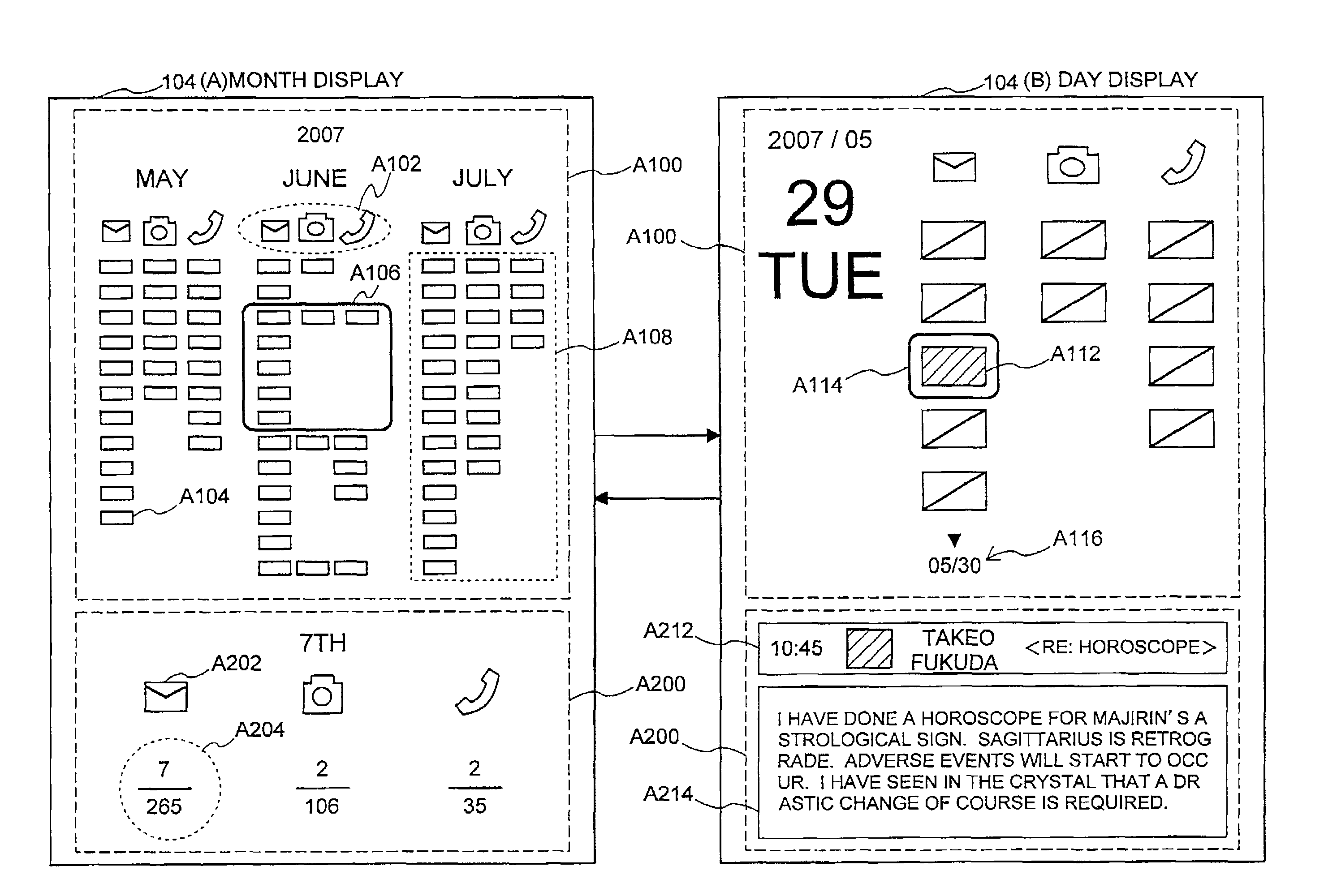
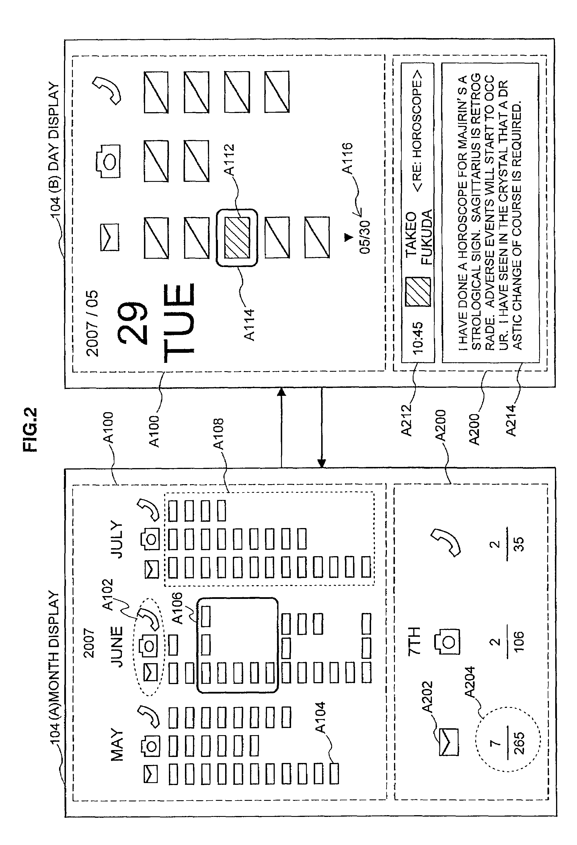
[0031]An embodiment according to the present invention will be explained in detail below. The present embodiment relates to a technology that provides a graphical user interface that is capable of making a user aware of relatedness among a plurality of types of content, based on time information that is included in the content. First, a configuration of a display system 1000 that is capable of providing the graphical user interface will be explained. Then specific examples of configurations of the graphical user interface according to the present embodiment will be shown, along with modified examples.

[0032]Configuration of Display System 1000

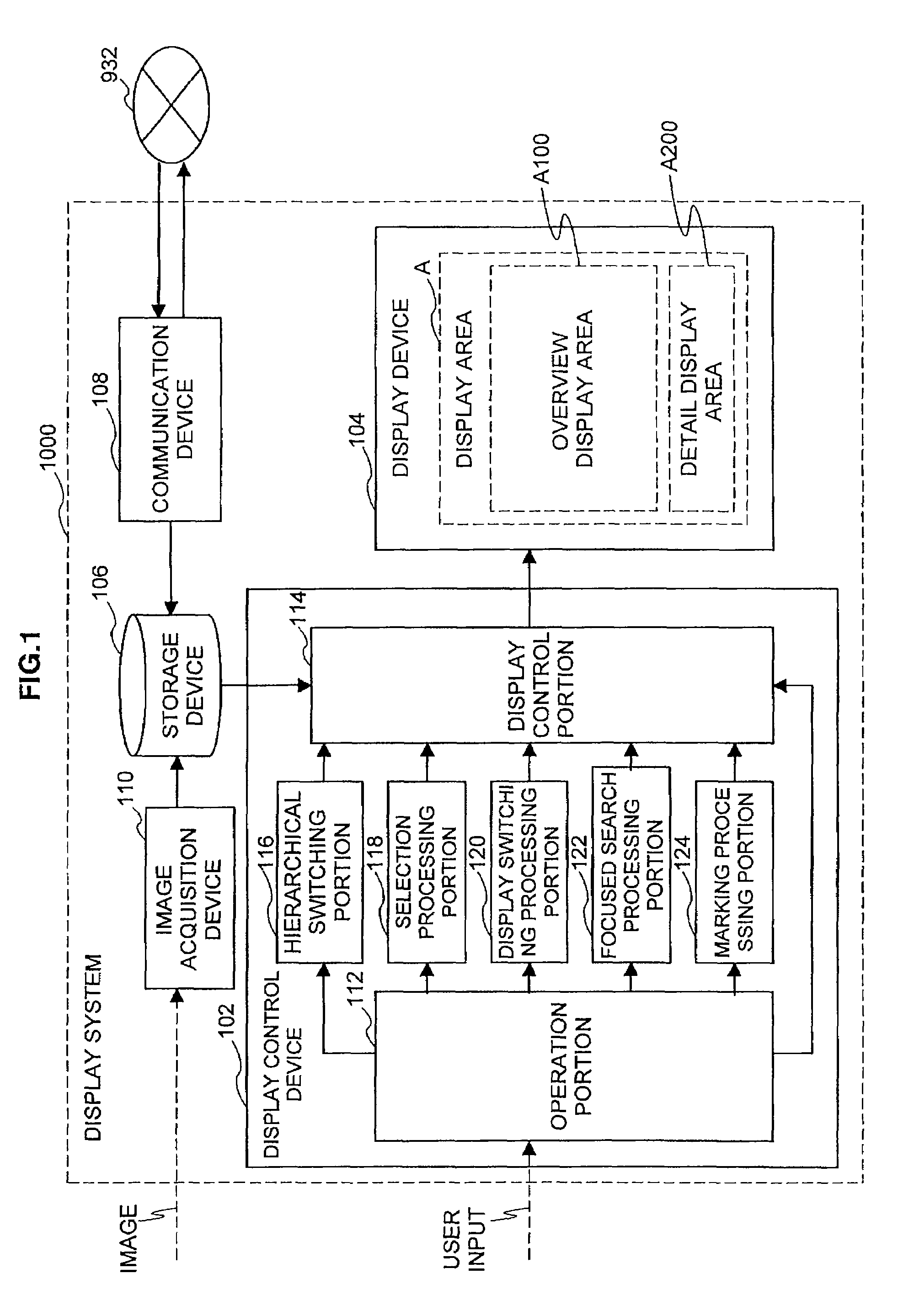
[0033]First, the configuration of the display system 1000 according to the present embodiment will be explained briefly with reference to FIG. 1. FIG. 1 is an explanatory figure that shows the configuration of the display system 1000 according to the present embodiment.

[0034]As shown in FIG. 1, the display system 1000 is mainly configured from a...


PUM


Abstract

There is provided a graphical user interface that is displayed within one screen of a display device. The graphical user interface includes a matrix-shaped display area that is partitioned along a first axis by types of content and partitioned along a second axis by units of time. Items of information on the content that is processed within a specified unit of time are displayed within the matrix-shaped display area, closed together along the second axis.

Description

CROSS REFERENCES TO RELATED APPLICATIONS[0001]The present invention contains subjected matter related to Japanese Patent Application JP 2007-211945 filed in the Japan Patent Office on Aug. 15, 2007, the entire contents of which being incorporated herein by reference.BACKGROUND OF THE INVENTION[0002]1. Field of the Invention[0003]The present invention relates to a graphical user interface, a display control device, a display method, and a program.[0004]2. Description of the Related Art[0005]In recent years, as information processing technologies have become more advanced, a variety of functions have been incorporated into small devices such as mobile telephones, game devices, and the like. In addition to communication functions and telephony functions, these devices are now equipped with a wide range of functions such as electronic mail functions, photography functions, schedule management functions, and the like. In order to use the various functions, a user of one of these devices ...

Claims


Application Information

Patent Timeline
Patent Type & Authority Patents(United States)
IPC IPC(8): G06F3/048G06F7/00
CPCG09G5/14H04M1/72566H04M1/72586G09G2340/12G09G2340/145H04M1/72552H04M2250/60H04M1/72436H04M1/72451H04M1/72472
Inventor IKEDA, TAKUOKARASAWA, HIDENORIMUGURA, KAZUTOIRIMAJIRI, MAYUKIMURA, SHINJIKUBOTA, YOSHIYASUKITAO, TAKASHISATO, SHOGOLI, DAN
Owner SONY CORP
Why Eureka
Eureka Blog
Learn More