
Angle-adjustable hinge

a technology of angle adjustment and hinge, which is applied in the direction of dismountable/non-dismountable seats, manufacturing tools, chairs, etc., can solve the problems of spoiled furniture design, large gear portion and toothed pieces, and limited attaching positions of angle adjustment hinges

Inactive Publication Date: 2012-01-31
KOYO GIKEN KK
View PDF16 Cites 25 Cited by
  • Summary
  • Abstract
  • Description
  • Claims
  • Application Information

AI Technical Summary

Benefits of technology

"The present invention provides an angle-adjustable hinge that can be used to adjust the angle of a back portion and armrest of a chair or other furniture. The hinge is small and thin, and can be embedded in the furniture without compromising its design. The hinge includes a pair of parallel wall portions, four wedge-shaped window portions, a pair of floating wedge members, gear portions, and cover members. The hinge is designed to support the load on the back portion and armrest, and can be used in various furniture such as chairs, massage chairs, headrests, and footrests. The hinge is attached to the furniture using attachment shafts and is unitedly fixed to the furniture using face contact and spot welding. The technical effect of the invention is to provide a thin and small angle-adjustable hinge that can be embedded in furniture without compromising its design."

Problems solved by technology

However, attachment positions of the angle-adjustable hinge having large gear portion and toothed piece are limited.
And, when the hinge is embedded in a sofa or a chair, a protrusion is generated and design of the furniture is spoiled.
And, simply making the gear portion thin, the gear portion may not be able to support the load of the person, and slip or damage may be generated on the engagement portion.

Method used


Image

  • Angle-adjustable hinge
  • Angle-adjustable hinge
  • Angle-adjustable hinge

Examples


first embodiment

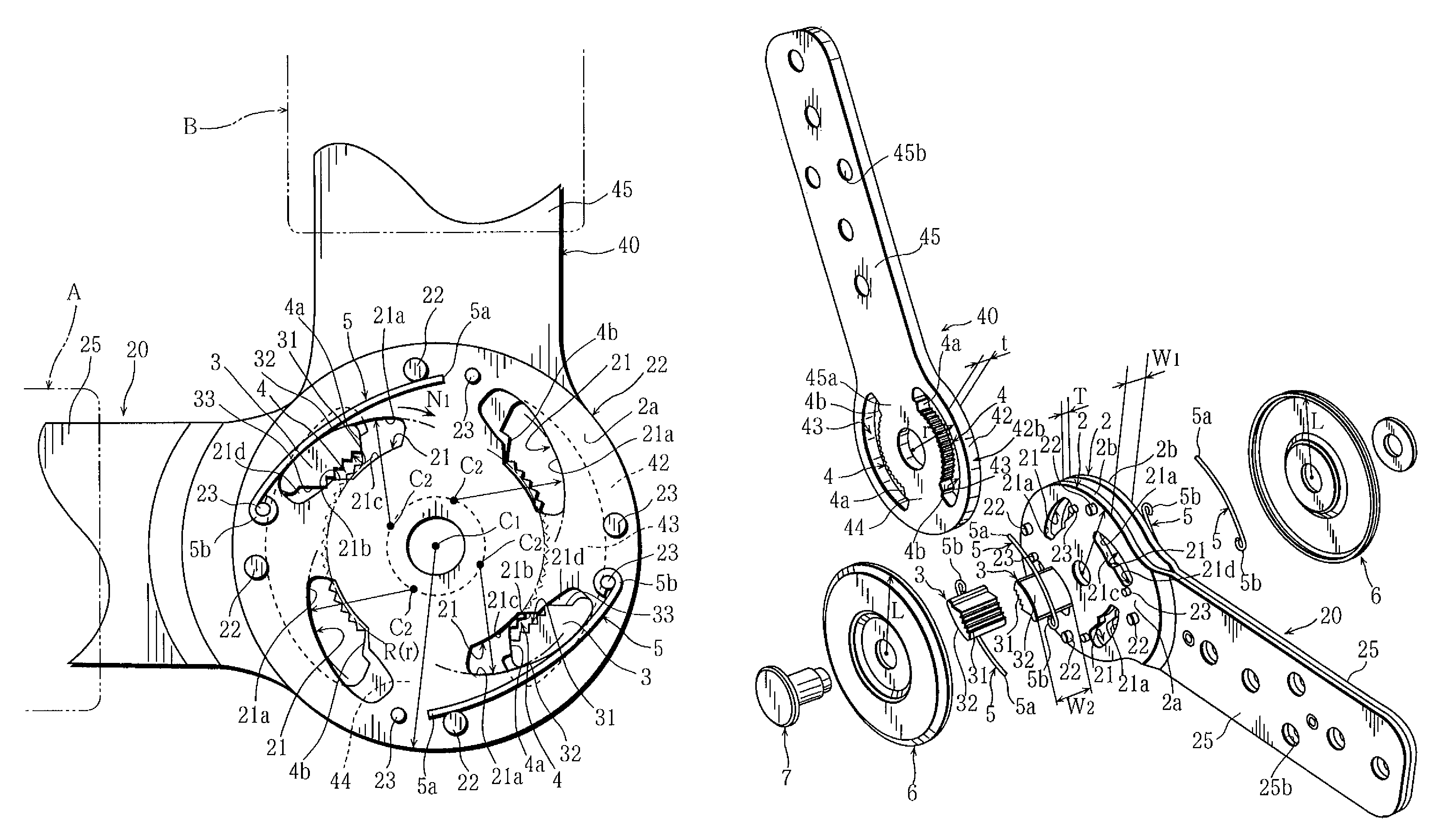
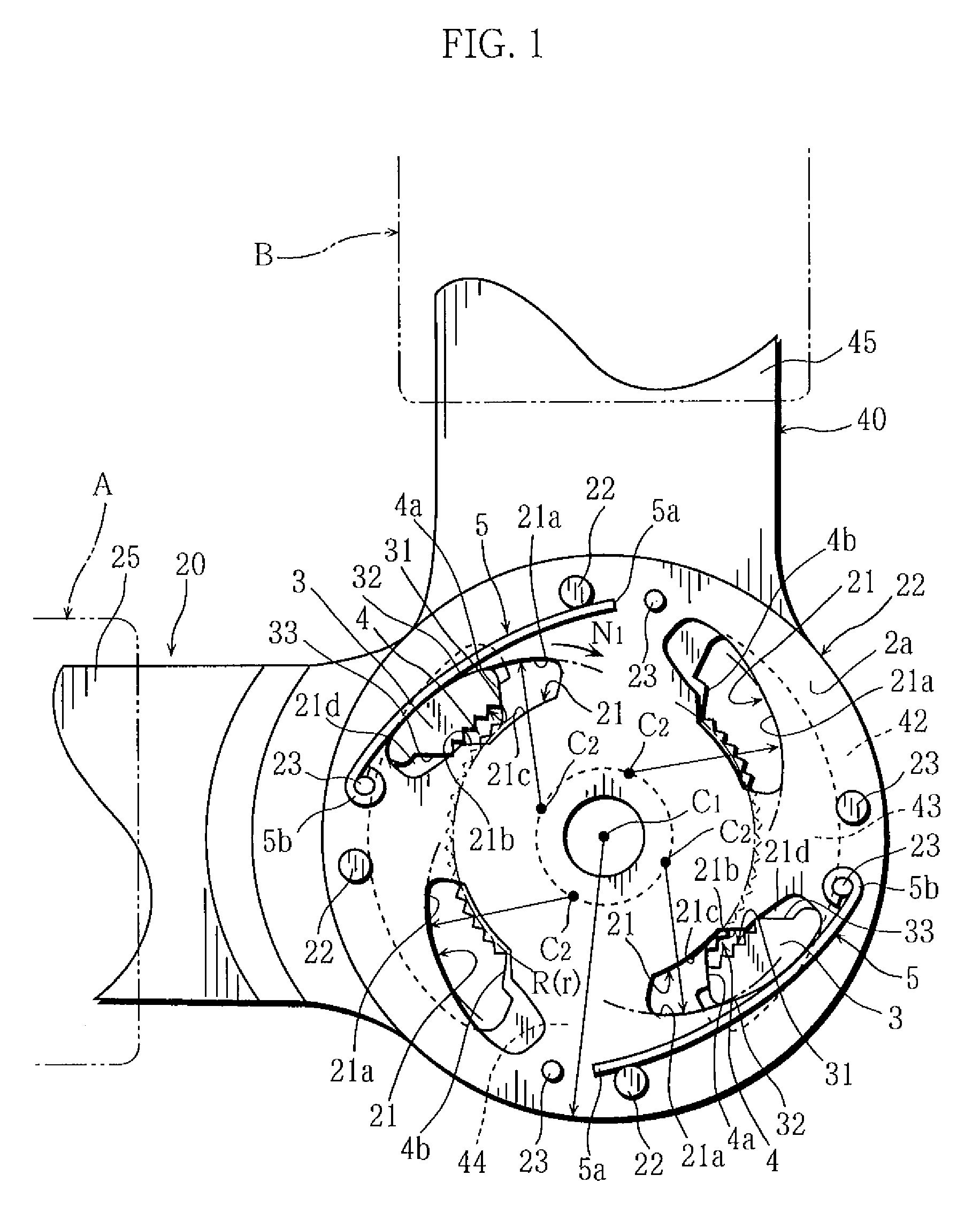
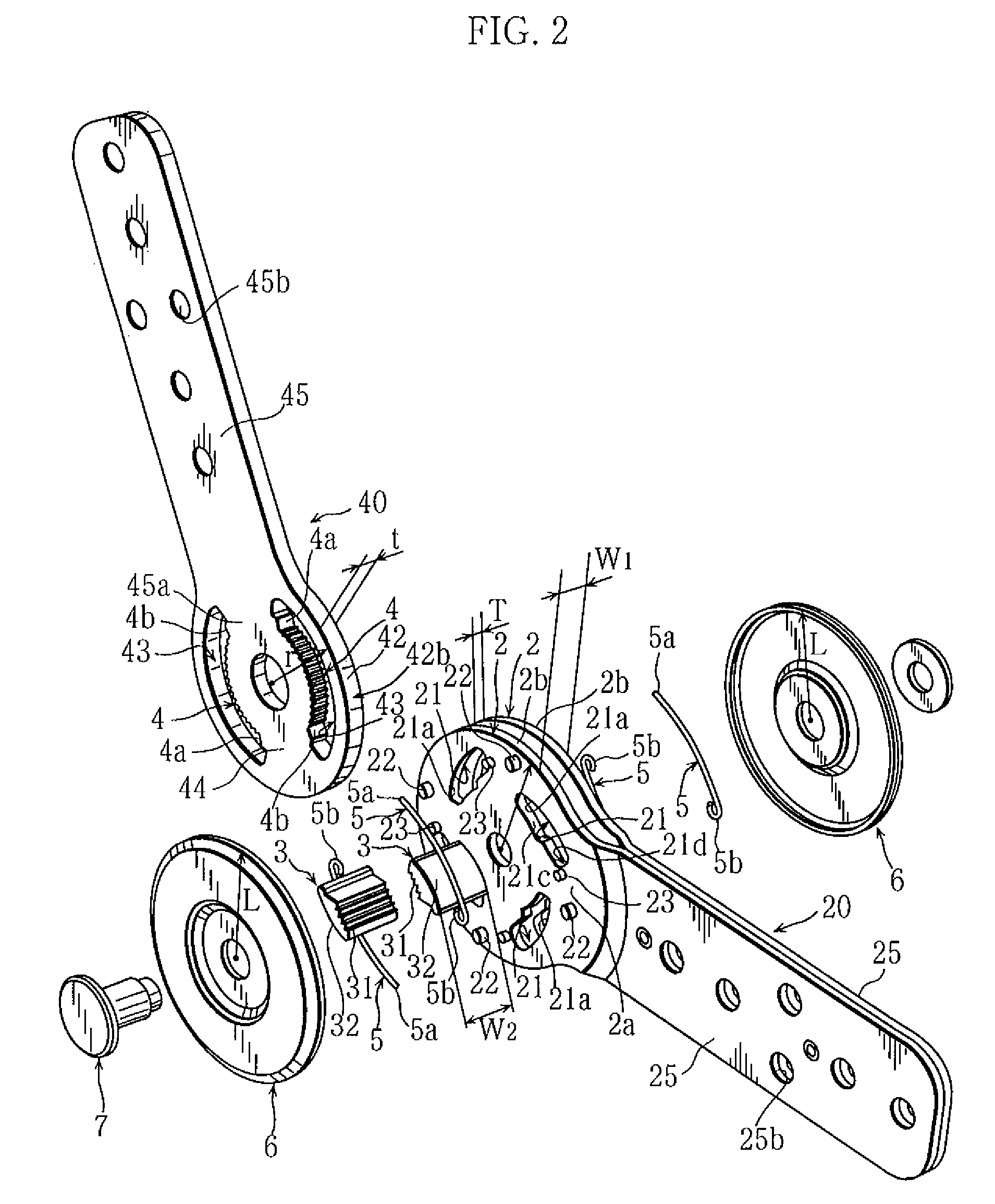
[0023]FIG. 1 is a side view of a principal portion showing an angle-adjustable hinge of the present invention. FIG. 2 is an exploded perspective view. FIG. 3 is a perspective view of an assembled state. FIG. 4 is a side view of a principal portion showing a state after an oscillation.

[0024]In the present invention, figures observed in a first axis C1 direction is called side views. And, “rotationally symmetric position of which axis of rotation is the first axis C1” may be called simply “rotationally symmetric position” for simple explanation.

[0025]The angle-adjustable hinge of the present invention is, for example, used as a hinge with which inclination angle of a back portion and armrest can be adjusted.

[0026]Other than chairs, massage chairs, headrests, footrests, etc., the hinge may be used to oscillatably connect two members such as in opening and closing doors.

[0027]In FIGS. 1 through 4, the hinge is provided with a pair of parallel wall portions 2 formed circular of which cen...

second embodiment

[0060]Next, a second embodiment is shown in FIG. 7.

[0061]The embodiment is provided with a pair of wall-portions 2, a pair of gear portions 4, and a pair of floating wedge members 3, and two wedge-shaped window portions 21 are disposed on each of the wall portions 2 on positions in rotation symmetry for 180° of which axis of symmetry is first axis C1. The floating wedge members 3 are respectively inserted to the wedge-shaped window portions 21. The wedge face 21a of the wedge-shaped window portion 21 is formed arc-shaped as to serially have the second axis C2, eccentric from the first axis C1 and rotation symmetric for every 180° around the first axis C1 as the axis of symmetry. Similar to the first embodiment, force (load) working on the gear portion 4 and the floating wedge member 3 is; supported by the pair of gear portions 4 and the pair of floating wedge members 3 disposed on the positions in rotation symmetry for 180°. Pressure is reduced by letting the floating wedge members ...


PUM


Abstract

An angle-adjustable hinge in which a pair of floating wedge members are disposed as to be rotation symmetric for 180° around a first axis as an axis of symmetry, and each of wedge faces of four wedge-shaped window portions is serially formed on an arc around a second axis as a center, eccentric from the first axis and rotation symmetric for every 90° around the first axis as the axis of symmetry.

Description

BACKGROUND OF THE INVENTION[0001]1. Field of the Invention[0002]This invention relates to an angle-adjustable hinge with which an angle formed by members on one side and another side can be set to a desired angle.[0003]2. Description of the Related Art[0004]Conventionally, as shown in Japanese utility model provisional publication number S59-20118, as an angle-adjustable hinge which can adjust oscillation angle as to set an angle of a back portion of a chair and a seat portion as a user desires, an hinge that holds the angle of the back portion to a desired position and restrict an oscillation in an inclining direction of the back portion by engagement of a toothed piece to a gear portion is known.[0005]When the angle of the back portion is held, stress on the engaged portion is reduced by forming the gear portion and the toothed piece large because the load of a person on the back portion is concentrated on the gear portion and the toothed piece.[0006]However, attachment positions ...

Claims


Application Information

Patent Timeline
Patent Type & Authority Patents(United States)
IPC IPC(8): E05D7/06
CPCA47C1/026B60N2/2356A47C7/38A47C7/506Y10T16/53848Y10T16/54025Y10T16/541Y10T16/54028Y10T16/54024Y10T16/5329Y10T16/5323B60N2/2352A47C7/5066A47C7/541B60N2/236B60N2/235
Inventor YAMASHITA, TADANOBU
Owner KOYO GIKEN KK
Learn More