Method for operating a resonance-measuring system and a resonance-measuring system

a technology of resonance measurement and measuring system, which is applied in the direction of mass flow measurement devices, measurement devices, instruments, etc., can solve the problems of high time consumption, inconvenient identification of parameters by identification methods, and high time consumption for determining parameters

Active Publication Date: 2012-01-31
KROHNE MESSTECHNICK GMBH & CO KG
View PDF2 Cites 7 Cited by
  • Summary
  • Abstract
  • Description
  • Claims
  • Application Information

AI Technical Summary

Benefits of technology

[0016]Thus, a primary object of the present invention is to provide a method for operating a resonance-measuring system—in particular a Coriolis mass flowmeter—in which identification of system-describing parameters is possible during operation—i.e., online—in a closed loop.

Problems solved by technology

These system parameters are normally in practice, however, time variant and can potentially change very quickly—or creeping—, which directly influences the quality of the measurement, in particular when the changes of these system parameters are unknown, which can be assumed for the most part.
The aforementioned examples clearly show that in order to achieve an accurate measurement result, it is necessary to know the essential system-describing parameters of the Coriolis mass flowmeter, since, inevitably, erroneous measurement results are achieved without this knowledge and a correspondingly erroneous adoption of the requirements forming the basis of the measurement.
Methods for determining the parameters of a structured system are essentially known from the prior art that work in an open loop; these types of identification methods are not suitable for carrying out a parameter identification on a Coriolis mass flowmeter during operation, at least not during controlled operation.
The method is very exact, but extremely time-consuming, since the system responses phase out very slowly due to the very weak damping of the measuring tube of the Coriolis mass flowmeter and, correspondingly, the time consumption for determining the parameters is quite high.
Beyond that, the method is not suitable for online parameter identification due to its use in open loop.
Compared to frequency response measurement having deterministic signals, this method is quicker due to the simultaneous excitation of the mass flowmeter to be identified in a broad frequency range, but it is also substantially less accurate.
Due to the high dynamics of the Coriolis mass flowmeter and due the influence of the measuring operation by the identification, this method can only be applied during regular operation with substantial limitations.

Method used


Image

  • Method for operating a resonance-measuring system and a resonance-measuring system
  • Method for operating a resonance-measuring system and a resonance-measuring system
  • Method for operating a resonance-measuring system and a resonance-measuring system

Examples


Embodiment Construction

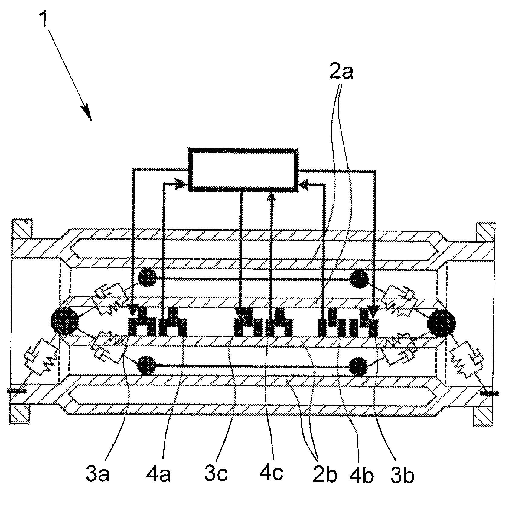
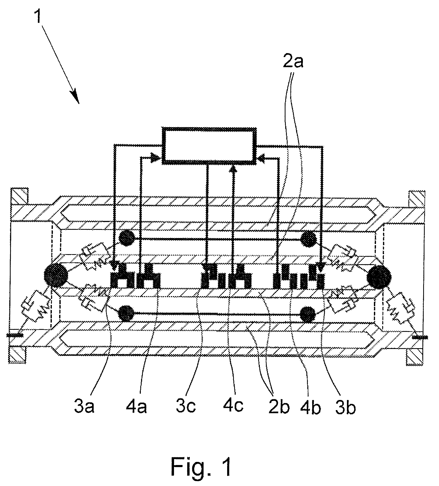
[0090]FIG. 1 shows a schematic representation of a Coriolis mass flowmeter 1 that is treated representatively for a general resonance measuring system and that is operated using the method being described here. Presently, the Coriolis mass flowmeter 1 has two measuring tubes 2a, 2b as oscillating elements interacting with the medium flow, three oscillation drivers 3a, 3b, 3c and three oscillation sensors 4a, 4b, 4c. The measuring tubes 2a, 2b are excited to oscillation in at least one eigenform by the oscillation drivers 3a, 3b, 3c by an excitation signal Fi(t) in a control in a—first illustrated in detail in FIG. 3—control loop 5, and the excited oscillation of the measuring tubes 2a, 2b is detected by the oscillation sensors 4a, 4b, 4c as a response signal yi(t) or as multiple response signals yi(t). In the measuring tubes 2a, 2b, the first eigenform of the excited oscillation forms only one bulge and the second eigenform forms an oscillation in which a central nodal point of the ...


PUM


Abstract

A method for operating a resonance-measuring system, in particular, a Coriolis mass flowmeter, having at least one oscillation element, at least one oscillation driver and at least one oscillation sensor, the oscillation element being excited to oscillation in at least one control using at least one control loop by at least one oscillation driver being excited by at least one excitation signal and the excited oscillations of the oscillation element being detected by the oscillation sensors as at least one response signal. At least one set variable of the closed loop is varied in a pre-determined manner and by evaluating at least one resulting excitation signal and / or at least one resulting response signal with the help of a mathematical model of the resonance-measuring system, at least one parameter of the excited eigenform is selectively identified.

Description

BACKGROUND OF THE INVENTION[0001]1. Field of Invention[0002]The invention relates to a method for operating a resonance-measuring system, in particular a Coriolis mass flowmeter, wherein the resonance-measuring system includes at least one oscillation element, at least one oscillation driver and at least one oscillation sensor, wherein the oscillation element (is excited to oscillation in at least one eigenform from at least one control in at least one control loop by at least one oscillation driver excited by at least one excitation signal and the excited oscillations of the oscillation element are detected by the oscillation sensors as at least one response signal. In addition, the invention relates to a resonance-measuring system that is operated using such a method.[0003]2. Description of Related Art[0004]Resonance-measuring systems of the type mentioned above have been known for years, not only in the form of Coriolis mass flowmeters, but also in density-measuring devices or le...

Claims


Application Information

Patent Timeline
Patent Type & Authority Patents(United States)
IPC IPC(8): G01F1/84
CPCG01F1/8436G01F1/8495
Inventor KOLAHI, KOUROSH
Owner KROHNE MESSTECHNICK GMBH & CO KG
Why Eureka
Try Eureka