Drain water bacteriostatic structure for air conditioner

a bacteriostatic unit and air conditioner technology, applied in the direction of functional valve types, lighting and heating apparatus, heating types, etc., can solve the problems of odor and clogging of drain pipes due to generation of slime, bacteria can multiply, complicated structure of drain pans, etc., to achieve stable and efficient bacteriostatic effects

Inactive Publication Date: 2012-01-31
DAIKIN IND LTD
View PDF13 Cites 18 Cited by
  • Summary
  • Abstract
  • Description
  • Claims
  • Application Information

AI Technical Summary

Benefits of technology

[0017]Accordingly, the predetermined length H is set to an appropriate length, taking the consumed amount into consideration in accordance with the water level, and thus, continuous use with a constant concentration is possible over a desired long period of time. In addition, this configuration can be gained by modifying only the configuration of the antibacterial member 50 with the configuration of the drain pan 8 left as it is in the prior art, and therefore, the drain water bacteriostatic structure is simple and inexpensive.
[0018]It is preferable for the above described antibacterial member 50 to be formed of a container 50A having a number of pores and an antibacterial agent 50B in granular form or pellet form contained within the container 50A. In this case, the antibacterial agent 50B in granular form or pellet form is eluted out from the antibacterial member 50 through the pores of the container 50A, and thus, pasteurizing effects are gained. Furthermore, the space created as a result of elution of the antibacterial agent 50B is supplied with a new antibacterial agent 50B located above, and lowers smoothly as a result of gravity.
[0019]At this time, it is preferable for the air conditioner 1 to have a drain pump 22 and for the antibacterial member 50 to be provided in a portion where the drain pump 22 is installed. In this case, microscopic vibration when the drain pump 22 is driven allows new antibacterial agent 50B to be supplied smoothly into the above described space from above, and thus, more stable supply of antibacterial agent 50B is possible.
[0020]In general, the above described antibacterial agent in granular form or pellet form is placed at random, and therefore, this configuration provides excellent effects for supplying the antibacterial agent 50B smoothly into the above described space from above. Furthermore, the portion where the drain pump 22 is installed is originally designated as maintenance space, and therefore, the antibacterial member 50 can be easily replaced after years of use.
[0021]In addition, it is preferable for the above described antibacterial member 50 to be formed of an antibacterial agent holding material 50D having water soluble properties and an antibacterial agent 50B in granular form or pellet form which is mixed in with the holding material 50D. In this case, as the antibacterial agent holding material 50D dissolves, the antibacterial agent 50B in granular form or pellet form is eluted, so that pasteurizing effects are gained. Furthermore, as the antibacterial agent holding material 50D dissolves, the antibacterial member 50 sinks smoothly as a whole as a result of gravity. Therefore, the pasteurizing effects are always sustained in a stable state.

Problems solved by technology

Therefore, bacteria can multiply in the drain water in the drain pan, and odor and clogging of the drain pipe due to generation of slime become a problem.
In any of the above described technologies, however, a problem arises in that the structure of the drain pan becomes complicated, and the bacteriostatic effects gradually decrease together with contamination, for example, through generation of slime.
Furthermore, in the case of the technology disclosed in Japanese Laid-Open Patent Publication No. 2000-97447, the configuration of some air conditioners makes it difficult to uniformly irradiate the entirety of the drain pan with ultraviolet rays using a single ultraviolet ray lamp, and thus, a number of ultraviolet ray lamps are necessary.
Therefore, there is a problem with this technology in that the cost for installing ultraviolet ray lamps and the operating costs both are high.
In this case, the above described initial concentration is much greater than the above described minimum concentration required, and a problem arises that the antibacterial agent is consumed in a wasteful manner.

Method used


Image

  • Drain water bacteriostatic structure for air conditioner
  • Drain water bacteriostatic structure for air conditioner
  • Drain water bacteriostatic structure for air conditioner

Examples


first embodiment

[0046]In the following, a drain water bacteriostatic structure for an air conditioner according to a first embodiment of the present invention is described.

[0047]First, FIGS. 1 and 2 show an example of a structure for an air conditioner to which the present invention is applicable.

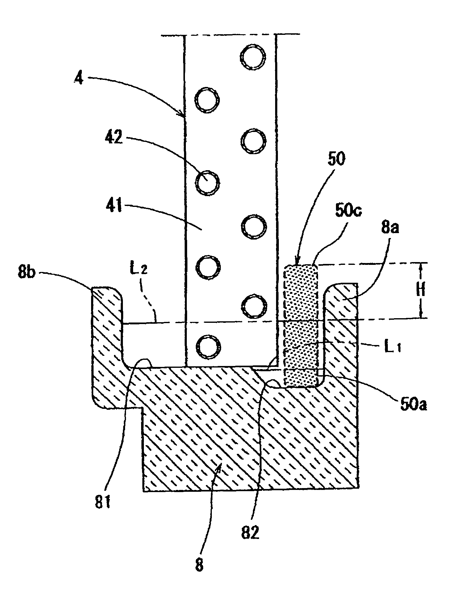
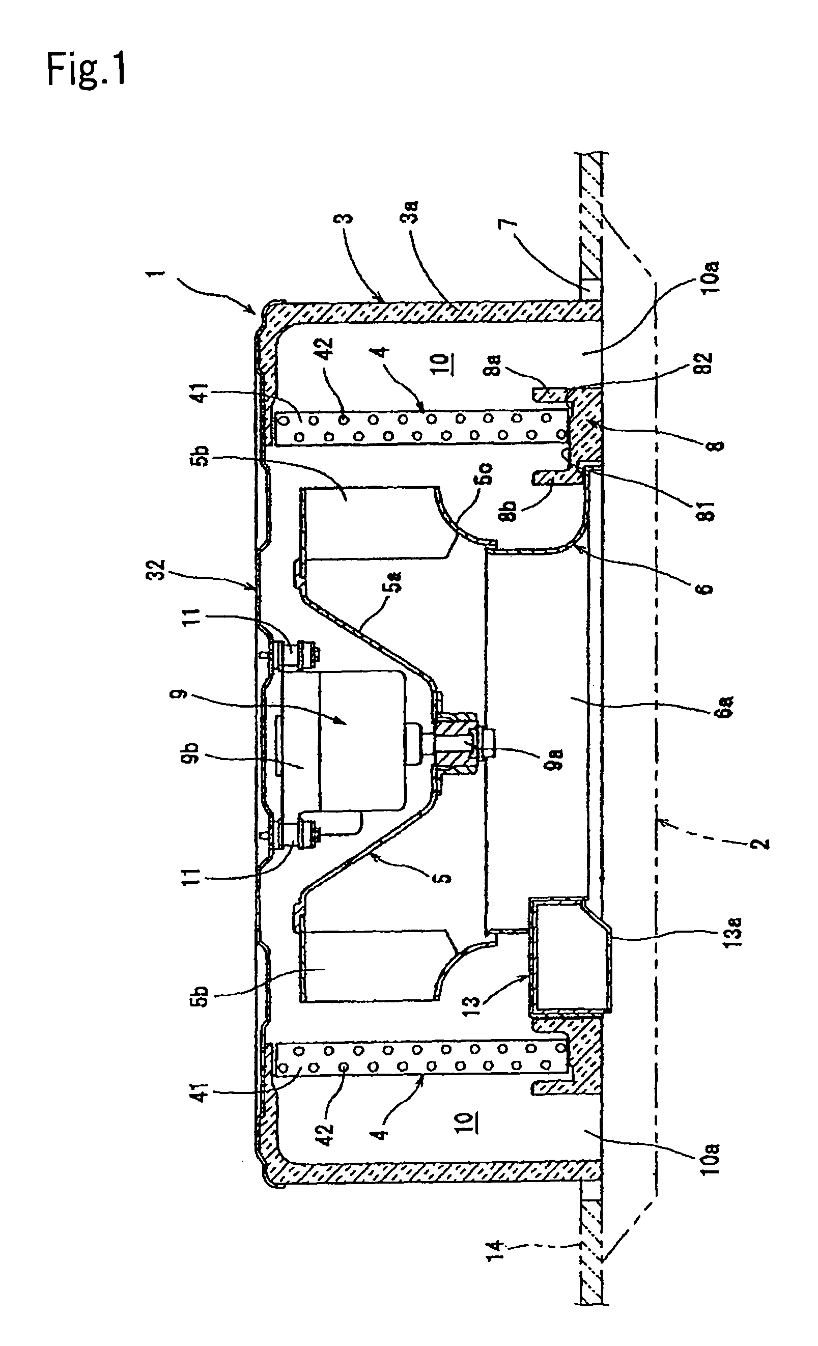
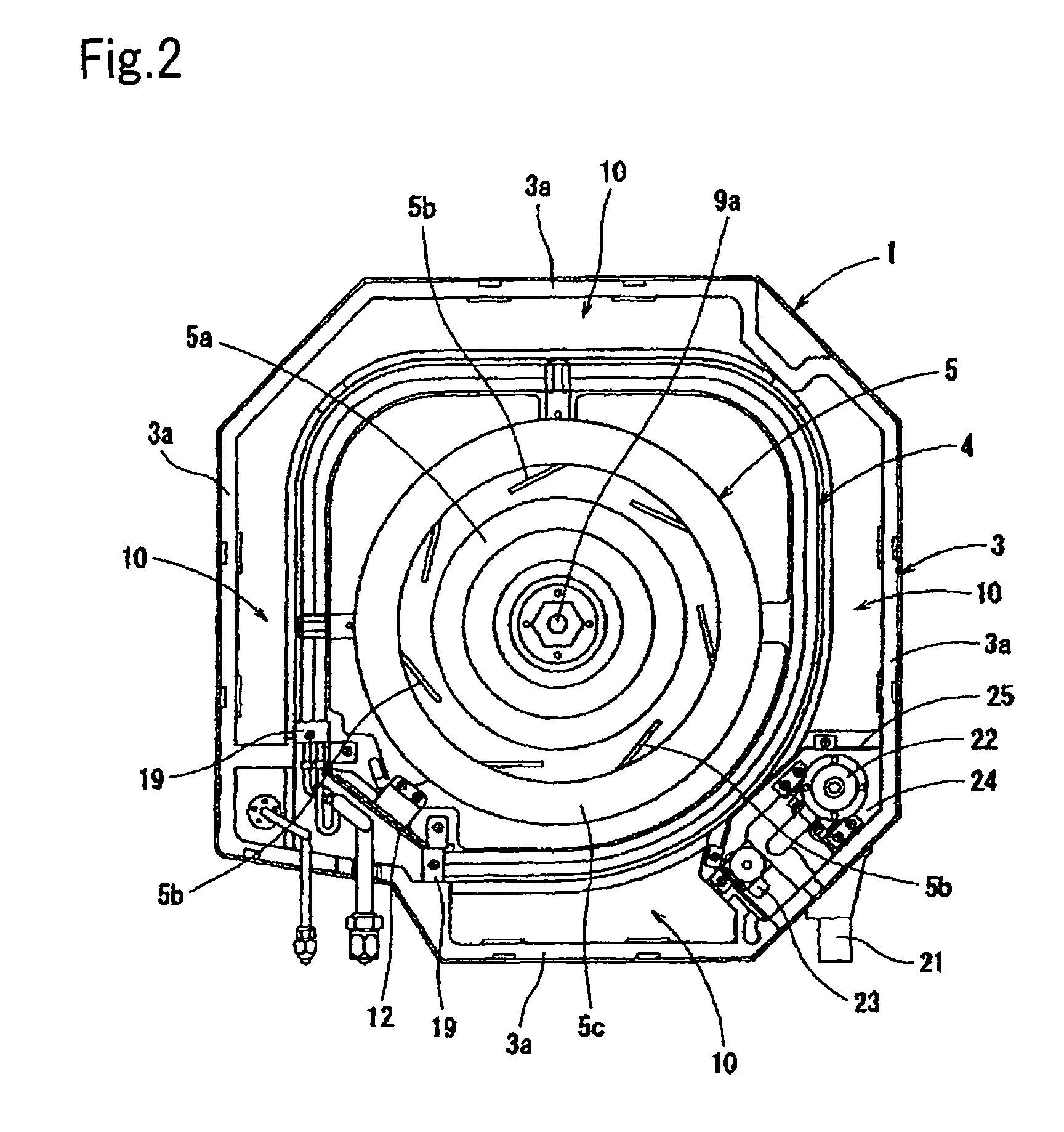
[0048]As shown in FIGS. 1 and 2, this air conditioner has an air conditioner main body 1 which is provided above an opening 7 created in a ceiling 14, and a face panel 2 for covering the opening 7, together with the air conditioner main body 1. The air conditioner main body 1 has a cassette type main body casing 3 in approximately hexagonal form, and a heat exchanger 4 in approximately annular form, a fan (radial impeller) 5, which is placed at the center of the heat exchanger 4 and of which the intake side faces downward and the side from which air is blown out faces the inner peripheral surface of the heat exchanger 4, and fan motor 9, and a bell mouth 6 (opening for air intake 6a), which is placed on th...

first modification

[0072]A first modification is the same as the above described first embodiment, except that the form of the antibacterial member 50 is changed to a flat cylindrical form, as shown in FIGS. 9 and 10. In this configuration also, exactly the same advantages as in the above described first embodiment can be gained.

[0073]In addition, in this configuration, the antibacterial member 50 can be easily installed, even in the case where the width of the second trench 82 in the drain pan 8 is small.

[0074]Furthermore, in this configuration, it is appropriate for the container main body 50A to be formed of, for example, a mesh member (made of a synthetic resin) having flexibility. In the case where the container main body 50A is formed of a mesh member, as shown in FIG. 11, one side and the two ends, upper and lower, of the mesh member are joined or sewn together in such a manner as to have a folded structure, and thus, the container main body 50A may be formed so as to be in the form of a flat b...

second modification

[0075]A second modification is the same as the above described first embodiment, except that the above described antibacterial member 50 is formed so as to be in columnar form by uniformly kneading the antibacterial agent 50B in granular form or pellet form into a synthetic resin material 50D, which is an antibacterial agent holding material having water solubility, as shown in FIGS. 12 and 13.

[0076]In the case of this configuration, as the synthetic resin material 50D and the antibacterial agent 50B, which are located in the lower end portion of the antibacterial member, 50 dissolve, the antibacterial member 50 becomes shorter. The antibacterial member 50 is simply held by holding means in one form or another in such a manner that it can slide down from above, and thus, it is possible for stable antibacterial effects to be sustained over a long period of time, with the antibacterial agent maintaining a constant concentration, in approximately the same manner as in the above describ...


PUM


Abstract

A drain water bacteriostatic structure for an air conditioner is provided with a drain pan 8 for holding drain water generated in an air conditioner 1 and an upright antibacterial member 50 which is provided in the drain pan 8. The antibacterial member 50 is provided with an antibacterial agent 50B. The length L3 of the antibacterial member 50 in the up-down direction is set such that the lower end portion 50a of the antibacterial member 50 is immersed in drain water when the drain water is at the minimum water level L1 in the drain pan 8, and the upper end portion 50b of the antibacterial member 50 is exposed above the maximum water level L2 of drain water in the drain pan 8 by a predetermined length H or more.

Description

TECHNICAL FIELD[0001]The present invention relates to a structure for a drain water bacteriostatic unit of an air conditioner.BACKGROUND ART[0002]A drain pan for receiving and discharging drain water to the outside is provided in the lower portion of heat exchangers in general-purpose air conditioners.[0003]Drain water held in a drain pan is discharged to the outside through a drain pipe from an inclined trench provided in the drain pan in the case of window type and wall type air conditioners, and through a drain pipe after being pumped up by a drain pump (including drain up kits) in the case of ceiling embedded-type and ceiling suspended air conditioners.[0004]In either case, however, drain water stays in the drain pan for a predetermined period of time. Therefore, bacteria can multiply in the drain water in the drain pan, and odor and clogging of the drain pipe due to generation of slime become a problem.[0005]As a measure against this, a technology for layering an antibacterial ...

Claims


Application Information

Patent Timeline
Patent Type & Authority Patents(United States)
IPC IPC(8): F24F13/00F16K23/00F24F1/0047F24F1/0063F24F13/22
CPCF24F1/0007F24F13/222F24F2001/0037F24F2003/1664F24F2013/228F24F1/0022F24F2013/0616F24F1/0047Y10T137/4891Y10T137/5762F24F8/20F24F1/0063F24F13/22F24F1/00
Inventor NAKATA, HARUOTAKEUCHI, MAKIO
Owner DAIKIN IND LTD
Why Eureka
Try Eureka