Angle detecting apparatus and angle detecting method

a technology of angle detection and angle detection, applied in the direction of measuring devices, instruments, using electrical means, etc., can solve the problems of imposing a limit on the detected angle, the angle of rotation detection apparatus, etc., and achieve the effect of convenient installation

Inactive Publication Date: 2012-01-31
TDK CORPARATION
View PDF7 Cites 29 Cited by
  • Summary
  • Abstract
  • Description
  • Claims
  • Application Information

AI Technical Summary

Benefits of technology

[0008]The angle detecting apparatus according to the present invention uses the rotor configured such that the distance between the two points where the straight line passing through the center of rotation of the rotor crosses the outer periphery of the rotor is constant. Thus, a signal obtained by performing differential operation on the detection signals from the paired first and second magnetic sensors arranged opposite each other is a substantial sine wave signal containing information on the angle of rotation of the rotor. Consequently, angle detection can be achieved with a reduced detection error over the entire angular range (0 degrees to 360 degrees). Furthermore, the rotor need not be attached to the end surface of a detection target. Thus, the angle detecting apparatus can be easily installed. Additionally, the paired magnetic sensors are preferably arranged at the same distance from the center of rotation. This is because when the output signals are sufficiently symmetric, the differential output signal is similar to a sine wave.
[0011]In the preferred embodiment of the present invention, the first magnetoresistance effect element comprises a first free magnetic layer whose longitudinal direction is set to align with a direction of the center of rotation of the rotor. The second magnetoresistance effect element comprises a second free magnetic layer whose longitudinal direction is set to align with the direction of the center of rotation of the rotor. By setting the longitudinal direction of the free magnetic layer to align with the direction of the center of rotation of the rotor, the accuracy of angle detection can be improved.
[0013]The angle detecting method according to the present invention uses the rotor configured such that the distance between the two points where the straight line passing through the center of rotation of the rotor crosses the outer periphery of the rotor is constant. Thus, a signal obtained by performing differential operation on the detection signals from the paired first and second magnetic sensors arranged opposite each other is a substantial sine wave signal containing information on the angle of rotation of the rotor. Consequently, angle detection can be achieved with a reduced detection error over the entire angular range (0 degrees to 360 degrees).
[0017]Another aspect of the present invention provides an angle detecting method of detecting an angle of rotation of a rotating shaft using a first magnetic sensor and a second magnetic sensor arranged at an equal distance from a center of rotation of a rotor fixed to the rotating shaft so as to have a phase difference of 90 degrees, the method comprising the steps of rotating the rotor together with the rotating shaft, wherein the rotor is such that a distance between two points where a straight line passing through the center of rotation of the rotor crosses the outer periphery of the rotor is constant; allowing a first detection signal to be output by the first magnetic sensor detecting a change in a magnetic field corresponding to a change in a first distance between the outer periphery of the rotor and the first magnetic sensor which distance varies periodically in conjunction with rotation of the rotor; allowing a second detection signal to be output by the second magnetic sensor detecting a change in a magnetic field corresponding to a change in a second distance between the outer periphery of the rotor and the second magnetic sensor which distance varies periodically in conjunction with the rotation of the rotor; creating a conversion table storing the angle of rotation of the rotating shaft corresponding to each of the first and second detection signals, and comparing the conversion table with each of the first and second detection signals output by the first and second magnetic sensors to output the angle of rotation of the rotor.
[0019]The present invention can provide an angle detecting apparatus and an angle detecting method in which the detected angle is not limited and the apparatus can be easily installed.

Problems solved by technology

However, the above-described angle of rotation detecting apparatus is disadvantageous in that a given limit is imposed on the detected angle (see FIG. 8B in Japanese Patent Laid-Open No. 2001-91208).

Method used


Image

  • Angle detecting apparatus and angle detecting method
  • Angle detecting apparatus and angle detecting method
  • Angle detecting apparatus and angle detecting method

Examples


embodiment 2

[0062]FIG. 11 is a diagram schematically illustrating the configuration of an angle detecting apparatus 100 according to Embodiment 2.

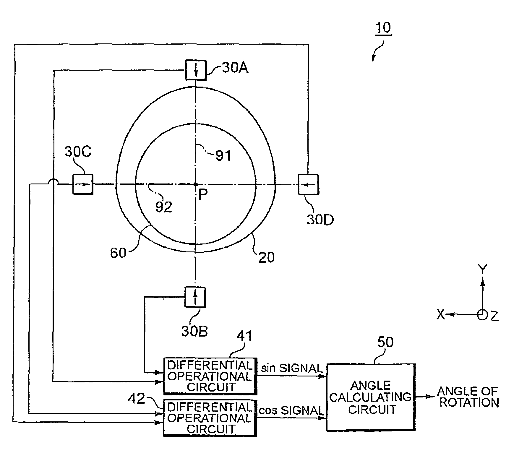
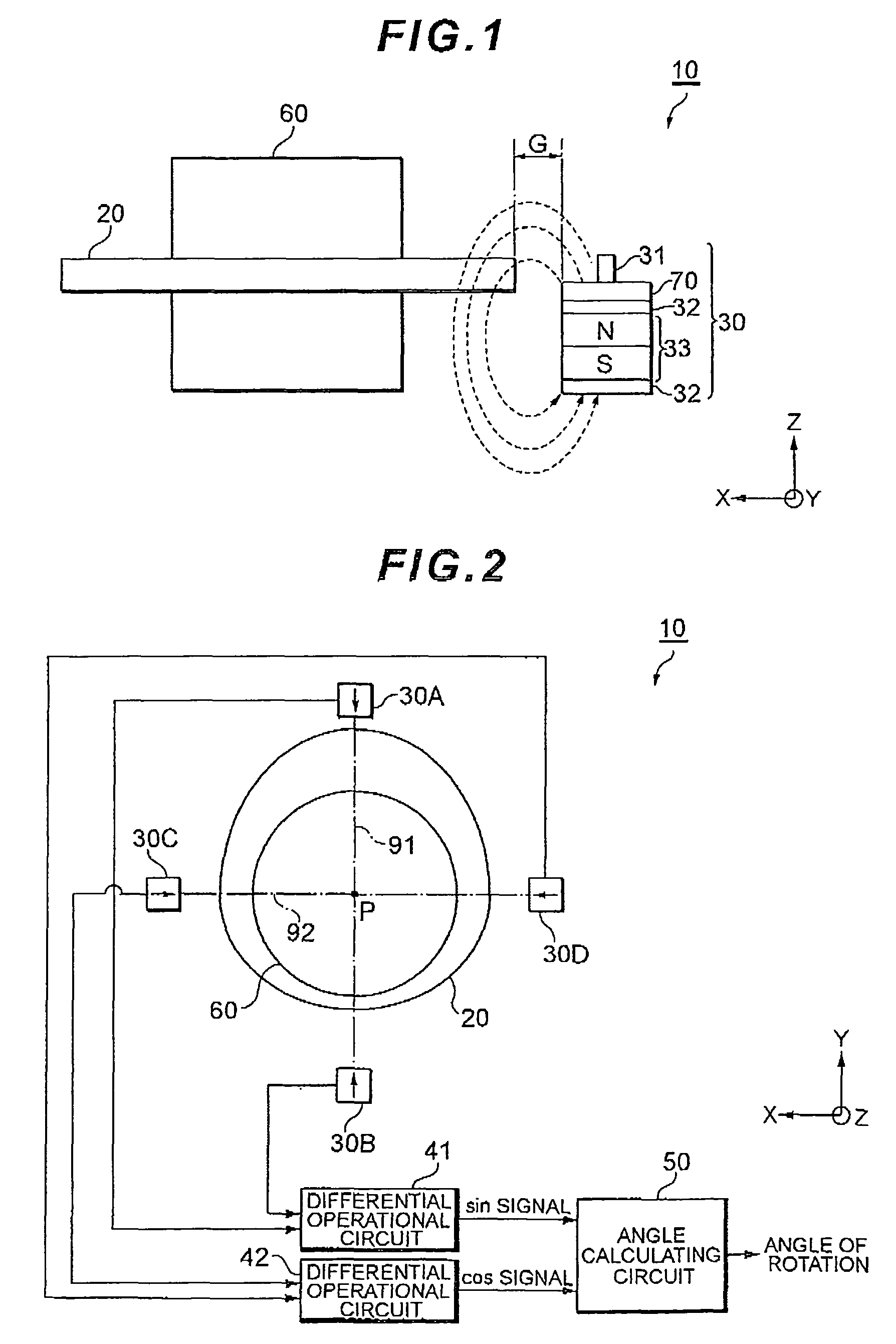
[0063]The angle detecting apparatus 100 includes, as main components, a rotor 20 fixed to a rotating shaft 60, two magnetic sensors 30E and 30F arranged close to the outer periphery of the rotor 20, and an angle calculating circuit 130 that outputs the angle of rotation of the rotor 20 based on detection signals output by the two magnetic sensors 30E and 30F. To be distinguished from each other, the magnetic sensors 30E and 30F are denoted by different reference numerals for convenience. However, the magnetic sensors 30E and 30F have substantially the same configuration as that of the magnetic sensor 30 shown in FIG. 1. The magnetic sensor 30E is positioned on an alternate long and short dash line 93 passing through the center of rotation P of the rotor 20. The magnetic sensor 30F is positioned on an alternate long and short dash line 94 passing throu...


PUM


Abstract

An angle detecting apparatus includes a rotor fixed to a rotating shaft, a pair of magnetic sensors arranged opposite each other so as to output a first detection signal and a second detection signal, respectively, each of which contains information on the angle of rotation of the rotor, a differential operational circuit performing differential operation on the first detection signal and the second detection signal, and an angle calculating circuit calculating the angle of rotation of the rotating shaft based on the result of the differential operation by the differential operational circuit. Here, the distance between two points where a straight line passing through the center of rotation of the rotor crosses the outer periphery of the rotor is constant.

Description

BACKGROUND OF THE INVENTION[0001]1. Field of the Invention[0002]The present invention relates to an angle detecting apparatus and an angle detecting method for calculating the angle of rotation of a rotating shaft.[0003]2. Description of the Related Art[0004]Japanese Patent Laid-Open No. 2001-91208 proposes an angle of rotation detecting apparatus as means for detecting the angle of rotation of a detection target such as a throttle valve. The angle of rotation detecting apparatus is configured such that a magnetic field is generated between a magnet and a yoke and that a magnetic detection element located in the magnetic field is displaced from the center of rotation of a rotor. Displacing the position of the magnetic detection element from the center of rotation of the rotor changes the relationship between the angle of a magnetic flux crossing the magnetic detection element and the angle of rotation of the rotor. This change can be utilized to optionally set the output property of...

Claims


Application Information

Patent Timeline
Patent Type & Authority Patents(United States)
IPC IPC(8): G01B7/30
CPCG01D5/145G01D5/24452G01D5/24476G01D5/2448G01D5/2449G01D18/001
Inventor KAITA, YOSHIOMIYAMOTO, HIROKAZUKIDO, TOSHINAO
Owner TDK CORPARATION
Why Eureka
Try Eureka