Passive optical network system and communication method therefor

a technology of optical network and communication method, applied in multiplex communication, exposure control, instruments, etc., can solve the problems of large expenses for the purpose of exchange, bringing about a comparatively high expense burden for carriers introducing pon and users utilizing pon, and achieve the effect of suppressing the exchange expense of communication devices

Inactive Publication Date: 2012-01-31
HITACHI LTD
View PDF4 Cites 12 Cited by
  • Summary
  • Abstract
  • Description
  • Claims
  • Application Information

AI Technical Summary

Benefits of technology

[0009]If the introduction and utilization modes of a PON are considered, notwithstanding the fact that the needs for the provision of higher-speed service capacity will gradually increase, it is not the case that the needs will all change in an instant, it being possible to consider that the utilization of unit of the users will start and gradually grow but that during this time, there will also exist in large numbers of subscribers finding the existing PONs to be sufficient. To exchange existing PONs with novel PONs, as mentioned above, amounts to carrying out an exchange of all OLTs and ONUs, so large expenses for the purpose of the exchange become necessary. Also, if one considers the essence of the aforementioned extension of communication capacity, it also leads to equipment exchange that is not yet necessary for some users and it can also lead to bringing about a comparatively high expense burden for carriers introducing PON and users utilizing PON. Because of this, there is demanded a PON, and a communication method therefor, with a structure making it possible to interconnect PON equipment with differing transmission speeds and switching over to a new PON that gradually accommodates existing PONs and making it possible to make coexist and operate a plurality of PONs having different specifications and performance.
[0011]The signals transmitted and received between the OLT and each ONU of the PON are constituted by control signals and overhead (headers) for carrying out settings and control of a system exchanging protocols, such as mentioned above, and signals (data, image signals, audio signals, and the like, hereinafter referred to very simply as “data”) transmitted and received by PON users via the OLT and the ONUs. Among these, headers (several tens of bytes) are added, for each frame with a 125 μs period, to the data transmitted and received by the user, but the control signal itself included in this header is transmitted and received once for several frames, after being processed inside the OLT and the ONU the setting and control of the PON is carried out. That is to say that the information itself of each header is not anything that needs to be sent at a positively high speed. On the other hand, the provision of high-speed service capacity requested by the user amounts to transmitting and receiving large volumes of data in a short time, so there is a need to transmit and receive at high speed in response to a request for data inside the frame.
[0019]By making it possible, in a PON in which communication signals from an OLT to a plurality of ONUs are multiplexed by time division and transmitted, to accommodate in coexistence a plurality of ONUs with differing transmission speeds, it becomes possible to suppress exchange expense of the communication devices even if there occurs a request for an extension of the communication service capacity, due to the fact that only the corresponding OLT and ONU exchange information.

Problems solved by technology

To exchange existing PONs with novel PONs, as mentioned above, amounts to carrying out an exchange of all OLTs and ONUs, so large expenses for the purpose of the exchange become necessary.
Also, if one considers the essence of the aforementioned extension of communication capacity, it also leads to equipment exchange that is not yet necessary for some users and it can also lead to bringing about a comparatively high expense burden for carriers introducing PON and users utilizing PON.
On the other hand, the provision of high-speed service capacity requested by the user amounts to transmitting and receiving large volumes of data in a short time, so there is a need to transmit and receive at high speed in response to a request for data inside the frame.

Method used


Image

  • Passive optical network system and communication method therefor
  • Passive optical network system and communication method therefor
  • Passive optical network system and communication method therefor

Examples


Embodiment Construction

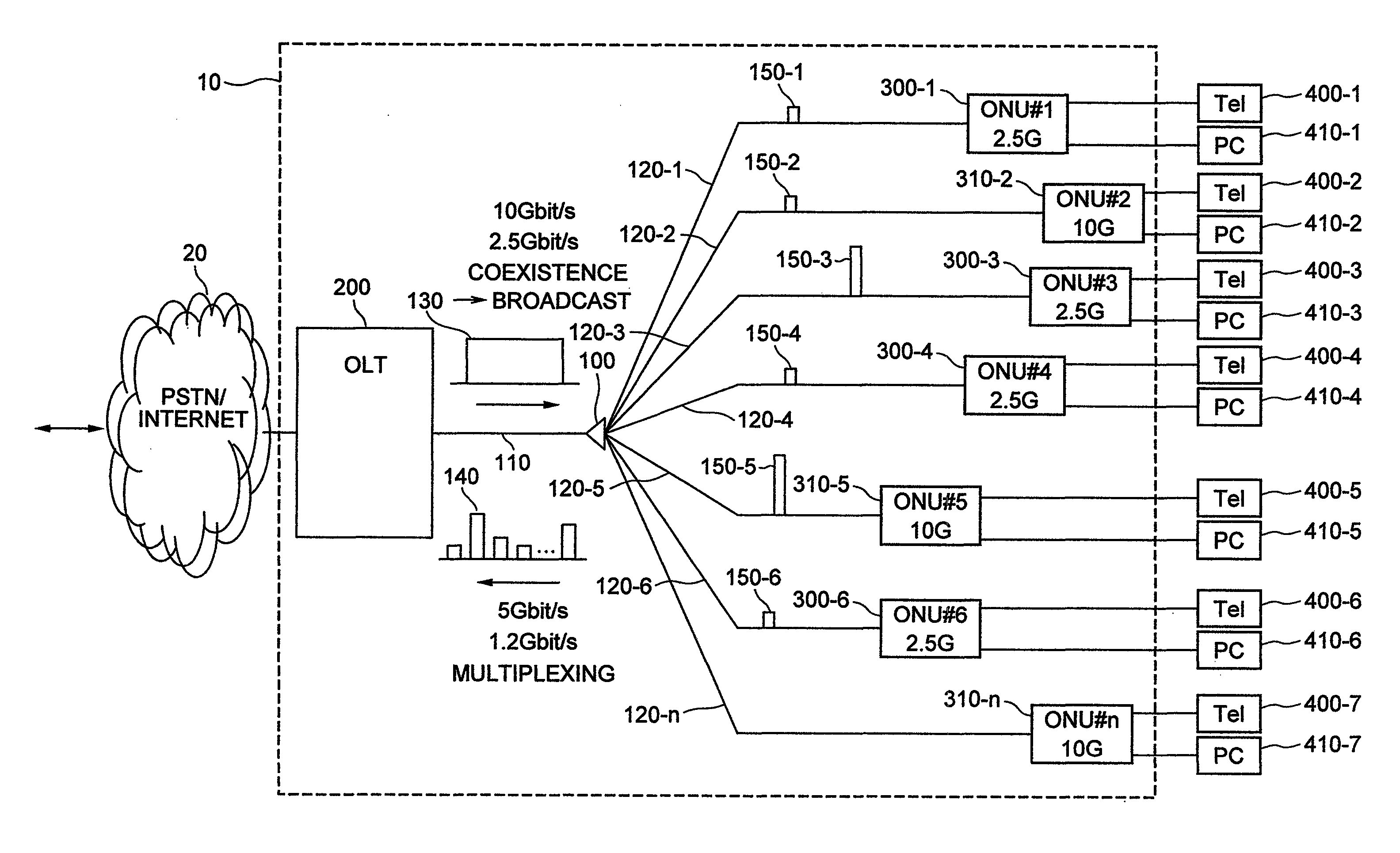
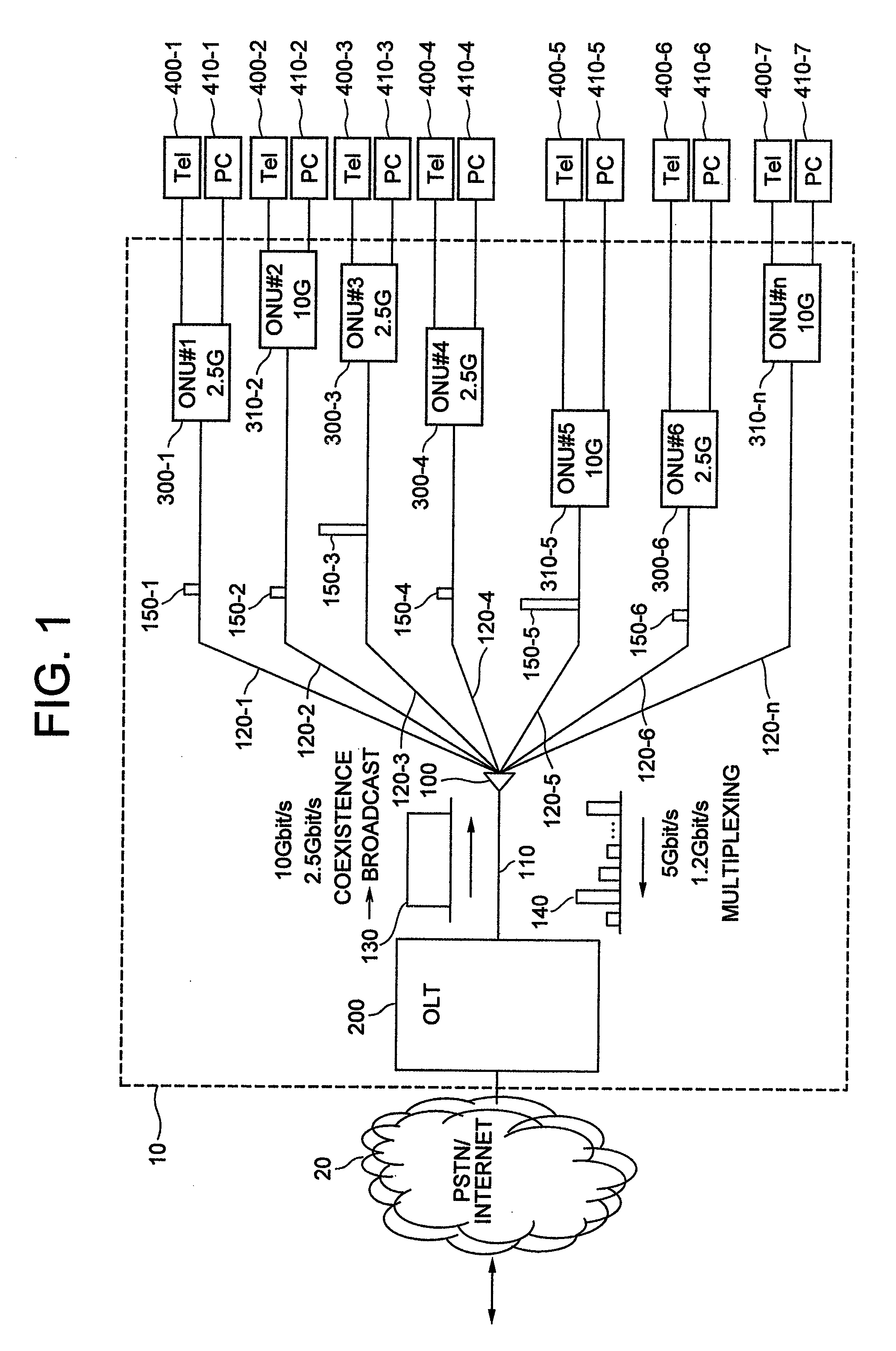
[0034]Hereinafter, there will be given an explanation in detail, using the drawings, of the structure and operation of a PON according to the present invention, and citing as an example the structure and operation of a PON in which there coexist a GPON specified in ITU-T Rec. G.984 and 10 GPON handling data at four times the transmission speed of GPON whose introduction is anticipated from now on.

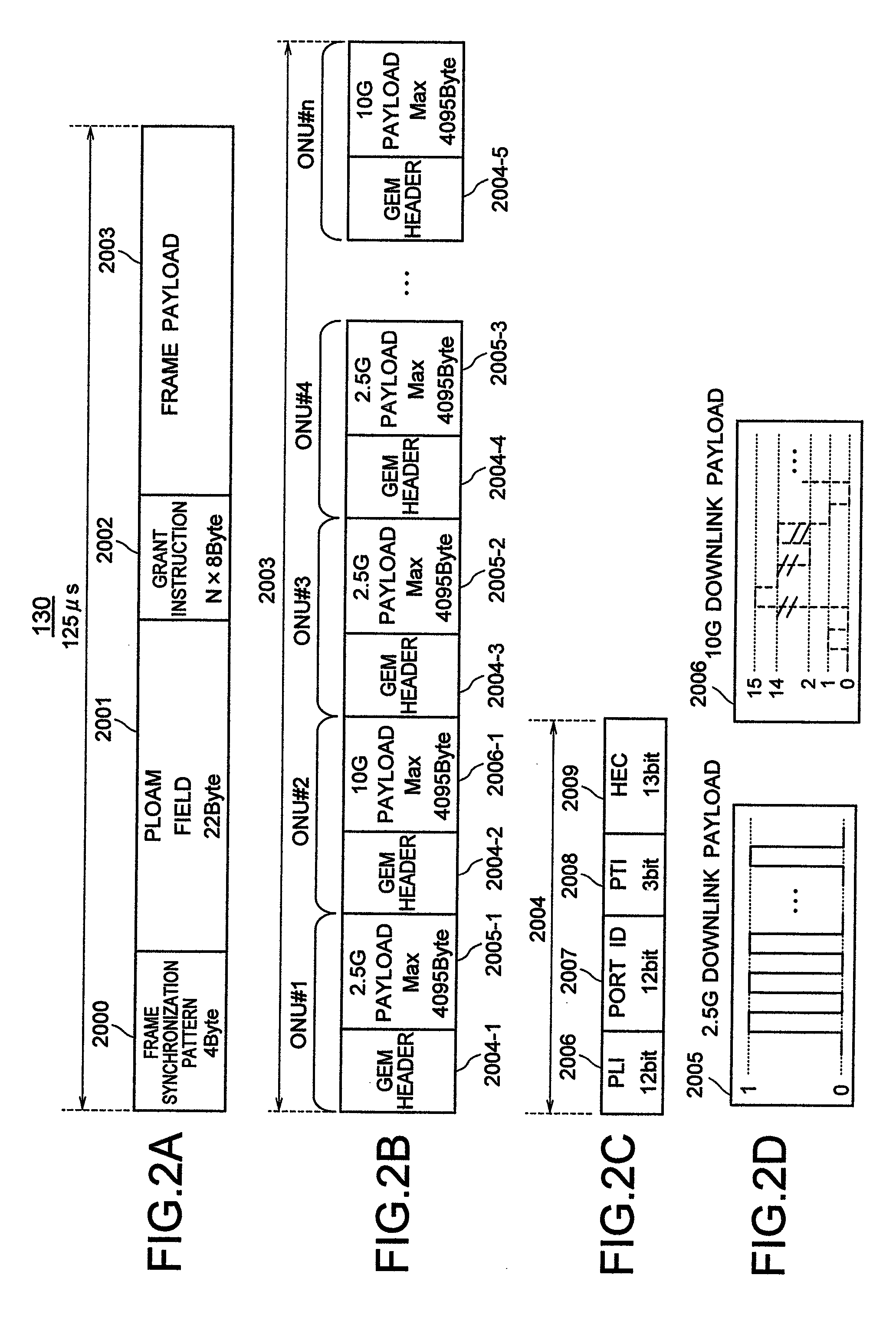
[0035]In the explanation below, the assumption is one of a PON with a structure, similar to that of GPON, that multiplexes by time division variable-length data and processes the same, and taking as examples, for the downlink data transmission speed from the OLT to each ONU, 2.5 Gbit / s (2.48832 Gbit / s but referred to below as 2.5 Gbit / s for simplification) of GPON and 10 Gbit / s (9.95328 Gbit / s but similarly referred to below as 10 Gbit / s) of 10 GPON. Also, as for the uplink data transmission speed from an ONU to the OLT, the explanation is given taking as examples 1.2 Gbit / s (1.24416 Gbit / s...


PUM


Abstract

In a passive optical network system in which communication signals from a master station to a plurality of subsidiary stations are multiplexed by time division and transmitted, after converting (modulating) data with a high transmission speed to a low transmission speed, a base speed, in the master station, a header including an identifier destined for each subsidiary station is attached to the data with a low transmission speed and the converted data, respectively, the data and the header being multiplexed by time division inside a frame and transmitted to the subsidiary stations at the base speed. In the subsidiary station having received the concerned frame, only the data destined for the station itself is read, on the basis of the identifier included in the header, and by means of demodulation, the converted data are reconverted to the original high speed data and supplied to a user terminal.

Description

INCORPORATION BY REFERENCE[0001]The present application claims priority from Japanese application JP2007-177936 filed on Jul. 6, 2007, the content of which is hereby incorporated by reference into this application.BACKGROUND OF THE INVENTION[0002]The present invention pertains to the structure of a passive optical network system, in which a plurality of subscriber connection devices share an optical transmission line, as well as a communication method therefor.[0003]In order to transmit and receive large-capacity signals and data via a communication network, the attainment of higher speeds and larger bandwidths of communication networks is being advanced as well in the access network connecting subscribers to a communication network, and the introduction of a Passive Optical Network (hereinafter referred to as “PON”) system specified in Recommendation G.984.1 to G.984.3 et cetera of the International Telecommunications Union (hereinafter referred to as “ITU-T”) is aimed for. A PON i...

Claims


Application Information

Patent Timeline
Patent Type & Authority Patents(United States)
IPC IPC(8): H04B10/00H04L12/44
CPCH04J3/0602H04J3/1694H04Q11/0067H04Q11/0071
Inventor TSUCHIYA, AKIHIKOYAJIMA, YUSUKEKAZAWA, TOHRU
Owner HITACHI LTD
Why Eureka
Try Eureka