Peel-away introducer sheath having pitched peel lines and method of making same

a technology of introducer and peel line, which is applied in the field of vascular introducers, can solve the problems of inability to evenly distribute the shearing force of peelable sheaths and slitting devices, difficulty in operation, and inability to provide separate devices. , to achieve the effect of evenly dispersing the sheering force, reducing the cost of providing a separate device, and reducing the cost of manual dexterity required to operate a slitter

Active Publication Date: 2009-01-29
OSCOR
View PDF16 Cites 8 Cited by
  • Summary
  • Abstract
  • Description
  • Claims
  • Application Information

AI Technical Summary

Benefits of technology

[0005]There are drawbacks associated with peelable sheaths and slitting devices. On one hand, peelable sheaths with straight score lines do not evenly distribute the shearing forces during peeling. This can make operation difficult or even result in malfunction such as partial or uneven separation. As for slitting devices, the expense of providing a separate device can be significant. Additionally, the manual dexterity required to operate a slitter can be undesirably high. There is a need, therefore, for an improved sheath which evenly distributes sheering forces, is efficient to fabricate and easy to use as well as assuring adequate separation.

Problems solved by technology

There are drawbacks associated with peelable sheaths and slitting devices.
On one hand, peelable sheaths with straight score lines do not evenly distribute the shearing forces during peeling.
This can make operation difficult or even result in malfunction such as partial or uneven separation.
As for slitting devices, the expense of providing a separate device can be significant.
Additionally, the manual dexterity required to operate a slitter can be undesirably high.

Method used


Image

  • Peel-away introducer sheath having pitched peel lines and method of making same
  • Peel-away introducer sheath having pitched peel lines and method of making same
  • Peel-away introducer sheath having pitched peel lines and method of making same

Examples


Embodiment Construction

[0021]The present disclosure overcomes many of the prior art problems associated with removing introducer sheaths. The advantages, and other features of the technology disclosed herein, will become more readily apparent to those having ordinary skill in the art from the following detailed description of certain preferred embodiments taken in conjunction with the drawings which set forth representative embodiments of the present invention and wherein like reference numerals identify similar structural elements.

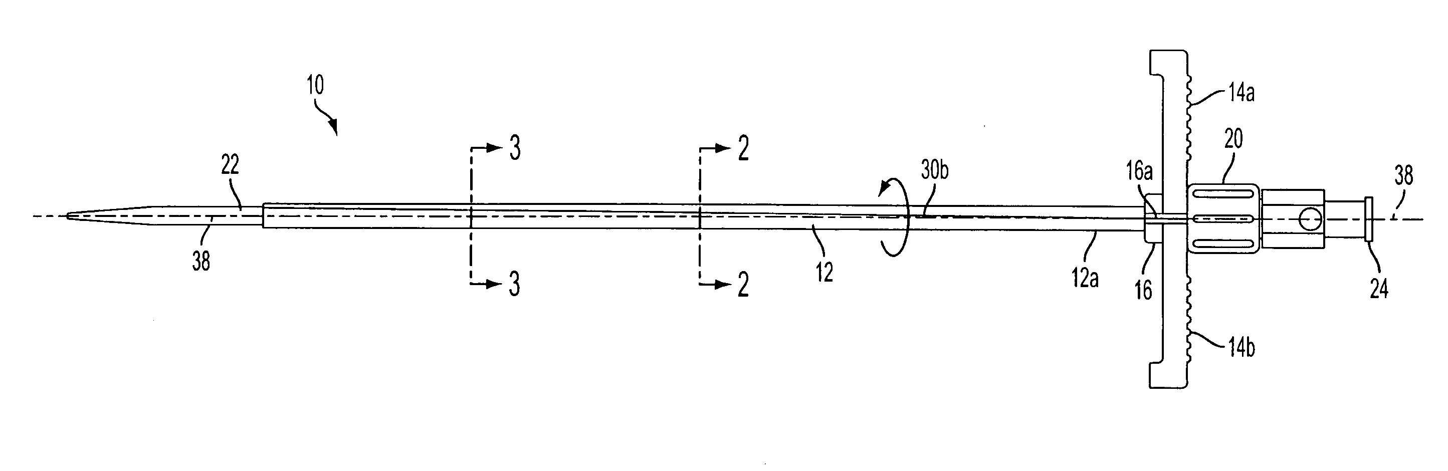
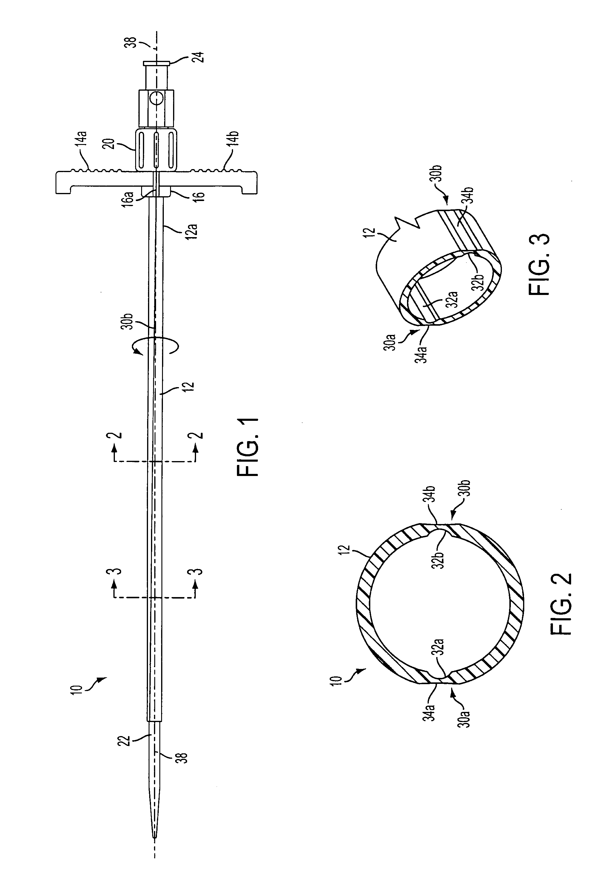
[0022]Referring now to FIG. 1, there is illustrated a vascular introducer assembly 10 that includes an elongated tubular sheath 12 defining opposed proximal and distal end portions 12a, 12b. A handle assembly 14 is operatively associated with the proximal end portion 12a of the tubular sheath 12. The handle assembly 14 includes a central hub 16 with a central parting line 16a defining a pair of opposed radially outwardly extending spreadable / separable handles 14a, 14b.

[0023]Th...


PUM

PropertyMeasurementUnit
wall thicknessaaaaaaaaaa
radius of curvatureaaaaaaaaaa
thicknessaaaaaaaaaa

Abstract

A percutaneous peel-away vascular introducer that includes an elongated tubular sheath having opposed proximal and distal ends, and a pair of diametrically opposed peel lines that extend along the length of the sheath from the proximal end thereof to the distal end thereof, wherein the diametrically opposed peel lines have an axially extending pitch. The introducer further includes a pair of spreadable handles associated with the proximal end of the sheath for splitting the sheath along the peel lines.

Description

CROSS-REFERENCE TO RELATED APPLICATION[0001]This application claims priority to U.S. Provisional Patent Application No. 60 / 961,856, filed Jul. 25, 2007, which is incorporated herein by reference.BACKGROUND[0002]The subject technology relates to a vascular introducer, and more particularly, to a vascular introducer having a peel-away sheath with pitched peel lines and to a method of forming the same by way of extrusion.[0003]Introducer devices have been employed for inserting catheters, guide wires, leads and the like into patients. A typical procedure provides for insertion of a dilator or needle encased within a sheath into the vasculature of a patient. After insertion, the dilator or needle may be removed leaving the sheath protruding from the patient's vein. The sheath is then removed. To remove the sheath, the sheath may be split or peeled away along two diametrically opposed score lines. Alternatively, the sheath may be slit open using a specialized cutting blade.[0004]Examples...

Claims


Application Information

Patent Timeline
Patent Type & Authority Applications(United States)
IPC IPC(8): A61M5/00D01D5/24B29C48/09B29C48/11B29C48/12
CPCA61M25/0668B29C47/0023B29K2995/0082B29C47/20B29L2031/7546B29C47/003B29C48/09B29C48/12B29C48/32B29C48/11B29C2793/0054
Inventor OSYPKA, THOMAS P.
Owner OSCOR
Why Eureka
Try Eureka