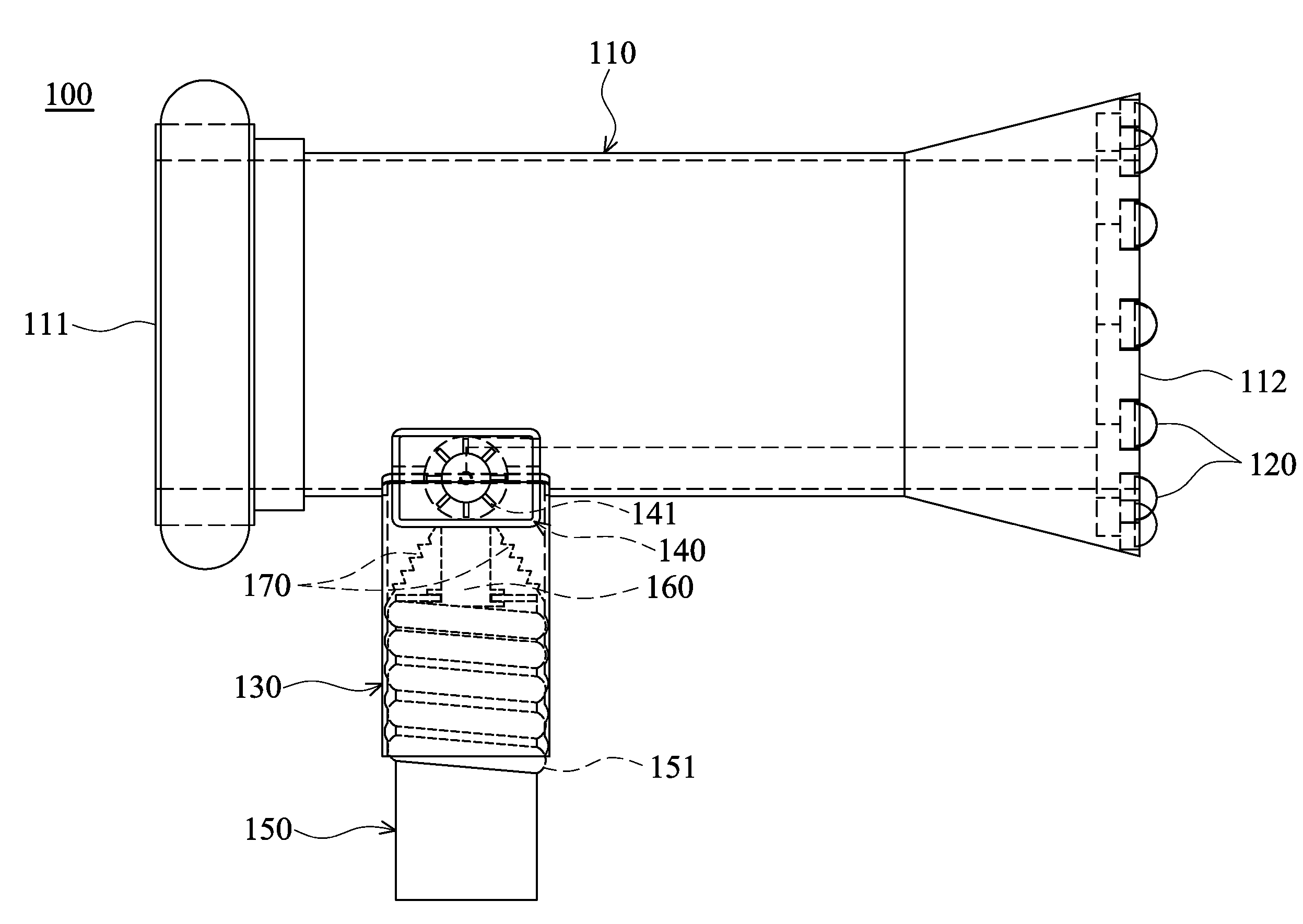
Illumination devices having movable fluid-driven generator
a technology of fluid-driven generator and illumination device, which is applied in the direction of semiconductor devices for light sources, lighting and heating equipment, and power sources with built-in, etc. it can solve the problems of loss of water pressure and amount, adversely affecting fire suppression, and firefighter inability to spare extra strength or a hand to hold the flashlight for illumination of fire scenes
- Summary
- Abstract
- Description
- Claims
- Application Information
AI Technical Summary
Benefits of technology
Problems solved by technology
Method used
Image
Examples
first embodiment
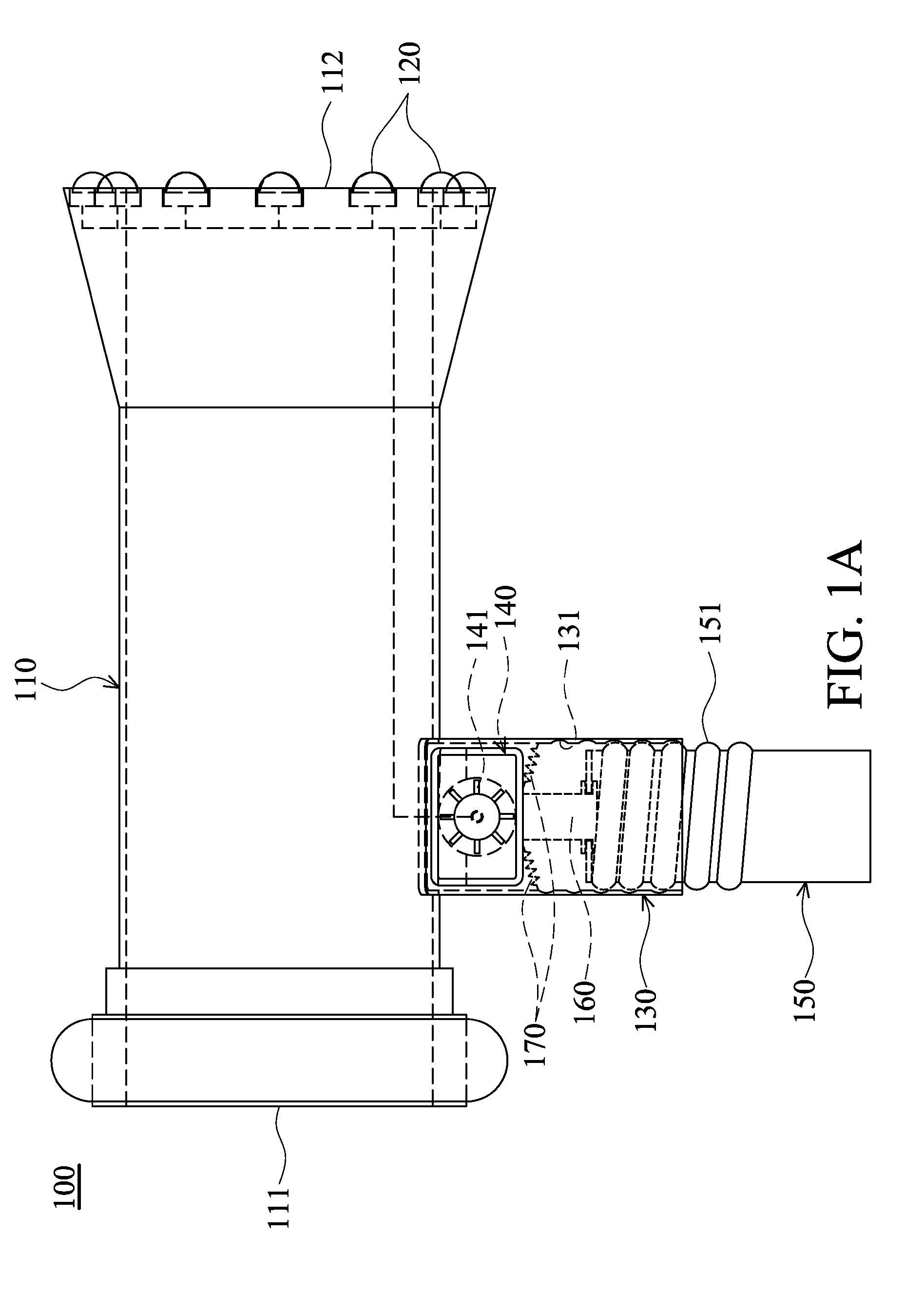
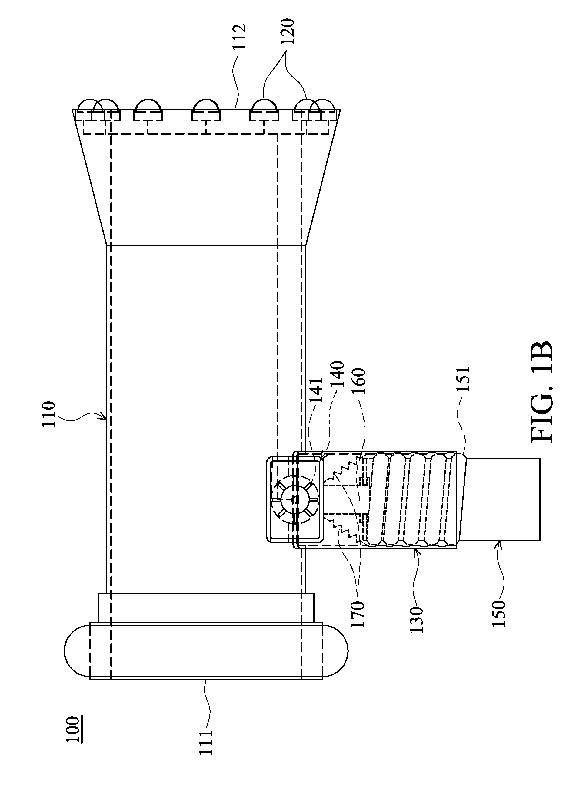
[0030]Referring to FIG. 1A and FIG. 1B, an adjustable fluid-driven illumination device 100 is applied for fire suppression and comprises a nozzle 110, a plurality of light-emitting elements 120, a grip 130, a turbine generator 140, a revolver 150, a push rod 160, and a plurality of resilient elements 170.
[0031]One end 111 of the nozzle 110 may connect to a fluid supply piping (not shown). In this embodiment, the nozzle 110 may serve as a fire-fighting nozzle.
[0032]The light-emitting elements 120 are connected to the nozzle 110. Specifically, the light-emitting elements 120 may be disposed on the other end 112 of the nozzle 110. Moreover, the light-emitting elements 120 may be high-brightness LEDs or light bulbs.
[0033]The grip 130 is connected to the nozzle 110. In this embodiment, the grip 130 is disposed between the end 111 and end 112 of the nozzle 110. Additionally, the grip 130 comprises an inner threaded portion 131.
[0034]The turbine generator 140 is electrically connected to t...
second embodiment
[0042]Referring to FIG. 2A and FIG. 2B, an adjustable fluid-driven illumination device 200 is applied for fire suppression and comprises a nozzle 210, a plurality of light-emitting elements 220, a grip 230, a turbine generator 240, a trigger 250, and a torsion spring 260.
[0043]One end 211 of the nozzle 210 may connect to a fluid supply piping (not shown). Similarly, the nozzle 210 may serve as a fire-fighting nozzle.
[0044]The light-emitting elements 220 are connected to the nozzle 210. Specifically, the light-emitting elements 220 may be disposed on the other end 212 of the nozzle 210. Moreover, the light-emitting elements 220 may be high-brightness LEDs or light bulbs.
[0045]The grip 230 is connected to the nozzle 210. In this embodiment, the grip 230 is disposed between the end 211 and end 212 of the nozzle 210.
[0046]The turbine generator 240 is electrically connected to the light-emitting elements 220 and comprises a plurality of rotating blades 241. Similarly, the rotating blades...
third embodiment
[0054]Referring to FIGS. 3A, 3B, and 3C, an adjustable fluid-driven illumination device 300 is applied for fire suppression and comprises a nozzle 310, a plurality of light-emitting elements 320, a grip 330, a turbine generator 340, a support rod 350, a fixed tube 360, a self-rotation shaft 370, a spring 380, and a button 390.
[0055]One end 311 of the nozzle 310 may connect to a fluid supply piping (not shown). Similarly, the nozzle 310 may serve as a fire-fighting nozzle.
[0056]The light-emitting elements 320 are connected to the nozzle 310. Specifically, the light-emitting elements 320 may be disposed on the other end 312 of the nozzle 310. Similarly, the light-emitting elements 320 may be high-brightness LEDs or light bulbs.
[0057]The grip 330 is connected to the nozzle 310. In this embodiment, the grip 330 is disposed between the end 311 and end 312 of the nozzle 310. Additionally, as shown in FIG. 3A and FIG. 3B, the grip 330 comprises a partition 331.
[0058]The turbine generator 3...
PUM
 Abstract
Description
Claims
Application Information
 - R&D
- Intellectual Property
- Life Sciences
- Materials
- Tech Scout
- Unparalleled Data Quality
- Higher Quality Content
- 60% Fewer Hallucinations
Browse by: Latest US Patents, China's latest patents, Technical Efficacy Thesaurus, Application Domain, Technology Topic, Popular Technical Reports.
© 2025 PatSnap. All rights reserved.Legal|Privacy policy|Modern Slavery Act Transparency Statement|Sitemap|About US| Contact US: help@patsnap.com


