Mechanical locking of floor panels

a technology of floor panels and locking mechanisms, applied in the direction of walls, building components, layered products, etc., can solve the problems of inability to connect floor panels, gap between the edge portions of short edges, and the risk of pushed away from each other, so as to reduce the separation force of short edges during installation or completely eliminate the effect of installation

Active Publication Date: 2012-02-14
VÄLINGE INNOVATION AB
View PDF214 Cites 148 Cited by
  • Summary
  • Abstract
  • Description
  • Claims
  • Application Information

AI Technical Summary

Benefits of technology

[0016]The present invention aims at a set of building panels, especially floor panels or a floating flooring with a mechanical locking system, preferably on the short edges, which is configured to improve installation of floor panels, preferably installed with vertical folding or vertical locking, such that separation forces of the short edges during installation are reduced or completely eliminated. The aim of the invention is also to simplify installation such that locking and preferably even unlocking could be accomplished without any vertical or horizontal pressure force or any displacement of the panels.
[0019]The invention offers the advantages that the panel edges will be locked in a first vertical direction and aligned when the edges are folded together and the protruding locking strip is cooperating with the adjacent edge. The magnetic tongue could then be displaced by a magnetic force into a locked position whereby the edges are locked in a second vertical direction. It is preferred that the tongue groove has an opening which is larger than the thickness of the outer part of the magnetic tongue such that a space exists between the tongue groove and the upper part of the magnetic tongue. The magnetic tongue will preferably only lock in a second vertical direction with its lower part against the lower part of the tongue groove and this will eliminate production tolerances and allow a displacement with a rather low pulling force.
[0022]The tongue-locking device prevents that the magnetic tongue moves in the groove when the magnetic force is removed. Such an embodiment offers several advantages. A long-term use with repeating pressures, applied at the edges by people walking on the floor, could cause a magnetic tongue to partly or completely move back towards the unlocked position if the locking system does not comprise a tongue-locking device. Such uncontrolled unlocking is a major problem especially in thin floating wood and laminate floors that are installed on a flexible underlay of, for example, foam and where the panel edges are displaced vertical when people walk over the floor surface.
[0023]Embodiments of the first aspect of the invention are concerned with several different types of tongue locking devices, e.g. a magnet arranged in an edge section of a panel, tongue locking protrusion, preferably with a vertical snap function, which protrudes vertically from the rest of the tongue or a tilt-able tongue with sharp edges. The tongue-locking device is preferably configured such that the tongue is easier to slide into the tongue groove and to the locked position compared to sliding in the reverse and un-locked direction. Specific embodiments comprise flexible tongue locking devices that are released when a magnetic force is applied and locked when a magnetic force is removed. Gravity and grooves that are not parallel with the main plane of the panel could also be used to prevent uncontrolled displacement. Displacement in two directions, for example perpendicularly to and parallel with the joint edge, could also be used and displacement towards an unlocked position could also be prevented, if a magnetic tongue located at a short edge is locked with its edge sections against long edges of adjacent panels in adjacent rows. The magnetic tongue could also comprise surfaces with different friction properties, which are active during locking and unlocking and could provide easy locking and considerable resistance against unlocking.
[0028]Locking and unlocking of a magnetic locking system is very simple. The magnet is just displaced from one edge to the other edge. The position of the magnet in relation to the joint edges could be used to indicate a locked and unlocked position.
[0029]Angling down and up again of a panel could be made in a simple way according to known technology since there is no tongue that creates any locking resistance as in the known vertical snap folding systems or vertical push folding systems. An additional advantage is that the magnetic tongue could be made rigid and preferably with a very simple, essentially rectangular form.

Problems solved by technology

The inventor has analysed several types of floor panels and discovered that there is a considerable risk that the short edges could be pushed away from each other during installation and that a gap could occur between the edge portions of the short edges.
Such a gap could prevent further installation and the floor panels will not be possible to connect.
It could also cause serious damage to the locking system at the short edges.
Such an installation method is however complicated and difficult to use since three actions have to be combined and used simultaneously in connection with angling down of the long edges.
This side push pressure parallel to the joint must be converted to a pressure force perpendicular to the edge and this is a disadvantage since a considerable part of the pressure will be lost and can not be used to create a strong locking force that brings the edges in the same plane in case that they are warped.
Most vertical push folding systems, especially such systems that comprise a flexible tongue that bends in the length direction of the joint, are difficult to lock when the first and the last rows are installed.
They are not suitable to lock wide panels.
This leads to the fact that expensive materials or complicated production methods must be used.
Matsushita teaches that such floorings cannot be provided with tongues.

Method used


Image

  • Mechanical locking of floor panels
  • Mechanical locking of floor panels
  • Mechanical locking of floor panels

Examples


Embodiment Construction

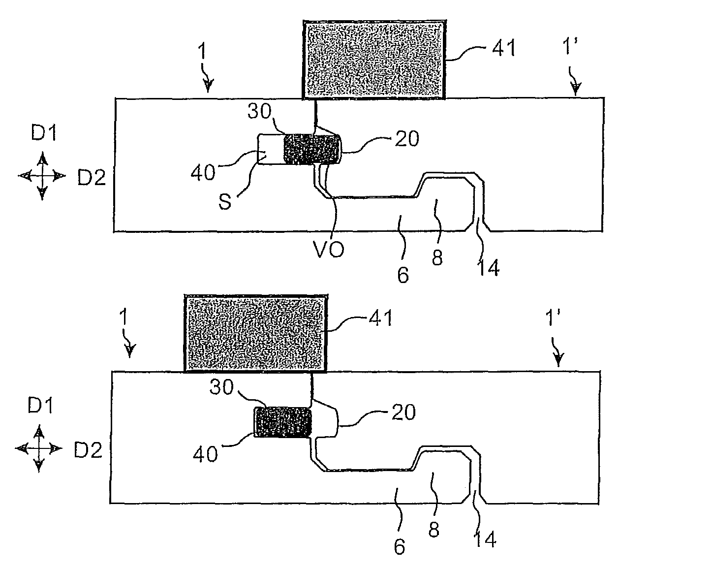
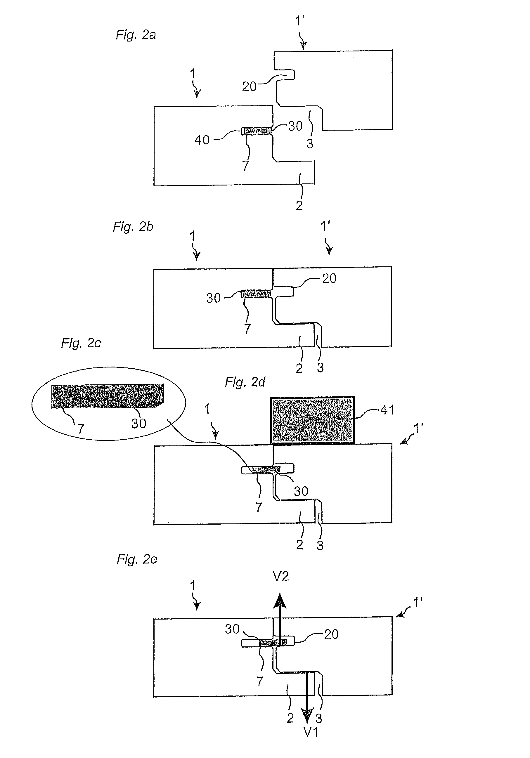
[0058]FIGS. 2a and 2b shows one embodiment of panels 1, 1′ with a magnetic locking system according to the invention. The locking system is in this embodiment of the invention used to lock two edges vertically V1, V2. A first panel 1 has a displaceable tongue 30 of magnetic material arranged in a displacement groove 40 formed in the edge of the first panel 1. The second panel 1′ comprises a tongue groove 20. The panels comprise a protruding locking strip 2 in one edge that cooperates with a cavity 3 in an adjacent edge and locks the edges in a first vertical direction V1 when the second panel 1′ is moved preferably vertically along a vertical plane VP and arranged in the same plane as the first floor panel 1. FIG. 2d shows that the magnetic tongue 30 is displaced horizontally into the tongue groove 20 when a magnet 41 is arranged on the floor surface, preferably essentially on the surface of the second panel 1′. The whole tongue 30 is displaced in the displacement groove. The tongue...


PUM


Abstract

Floor panels are shown, which are provided with a mechanical locking system having tongue of magnetic material that could be locked vertically by a magnetic field.

Description

AREA OF INVENTION[0001]The invention generally relates to the field of floor panels with mechanical locking systems comprising a separate displaceable tongue allowing easy installation. The invention provides new improved locking systems and methods to install and disconnect building panels, especially floor panels and methods to produce the locking system.BACKGROUND OF THE INVENTION[0002]In particular, yet not restrictive manner, the invention concerns a mechanical locking system for rectangular floor panels with long and short edges. It should be emphasized that long and short edges are only used to simplify the description. The panels could also be square, they could have more than 4 edges and the adjacent edges could have angles other than 90 degrees. However, the invention is as well applicable to building panels in general. More particularly the invention relates mainly to the type of mechanically locking systems, which allow that angling of long edges and vertical movement of...

Claims


Application Information

Patent Timeline
Patent Type & Authority Patents(United States)
IPC IPC(8): E04B2/00
CPCE04F15/02E04F21/22E04F15/02038E04F15/04E04F2201/0138E04F2201/0153Y10T428/167E04F2201/0541E04F2201/0547Y10S52/04E04F2201/0523E04F2201/06
Inventor PERVAN, DARKOPETERSON, JAN
Owner VÄLINGE INNOVATION AB
Why Eureka
Try Eureka