Mechanical locking of floor panels

Active Publication Date: 2010-12-23
VÄLINGE INNOVATION AB
View PDF99 Cites 187 Cited by
  • Summary
  • Abstract
  • Description
  • Claims
  • Application Information

AI Technical Summary

Benefits of technology

[0016]The present invention aims at a set of building panels, especially floor panels or a floating flooring with a mechanical locking system, preferably on the short edges, which is configured to improve installation of floor panels, preferably installed with vertical folding or vertical locking, such that

Problems solved by technology

The inventor has analysed several types of floor panels and discovered that there is a considerable risk that the short edges could be pushed away from each other during installation and that a gap could occur between the edge portions of the short edges.
Such a gap could prevent further installation and the floor panels will not be possible to connect.
It could also cause serious damage to the locking system at the short edges.
Such an installation method is however complicated and difficult to use since three actions have to be combined and used simultaneously in connection with angling down of the long edges.
This side push pressure parallel to the joint must be conv

Method used


Image

  • Mechanical locking of floor panels
  • Mechanical locking of floor panels
  • Mechanical locking of floor panels

Examples


Example

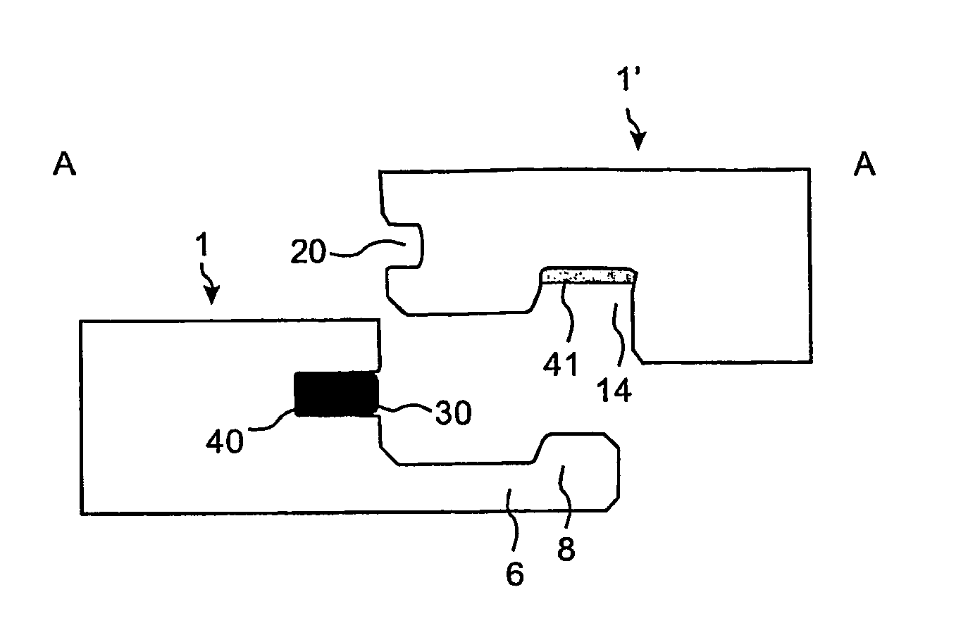
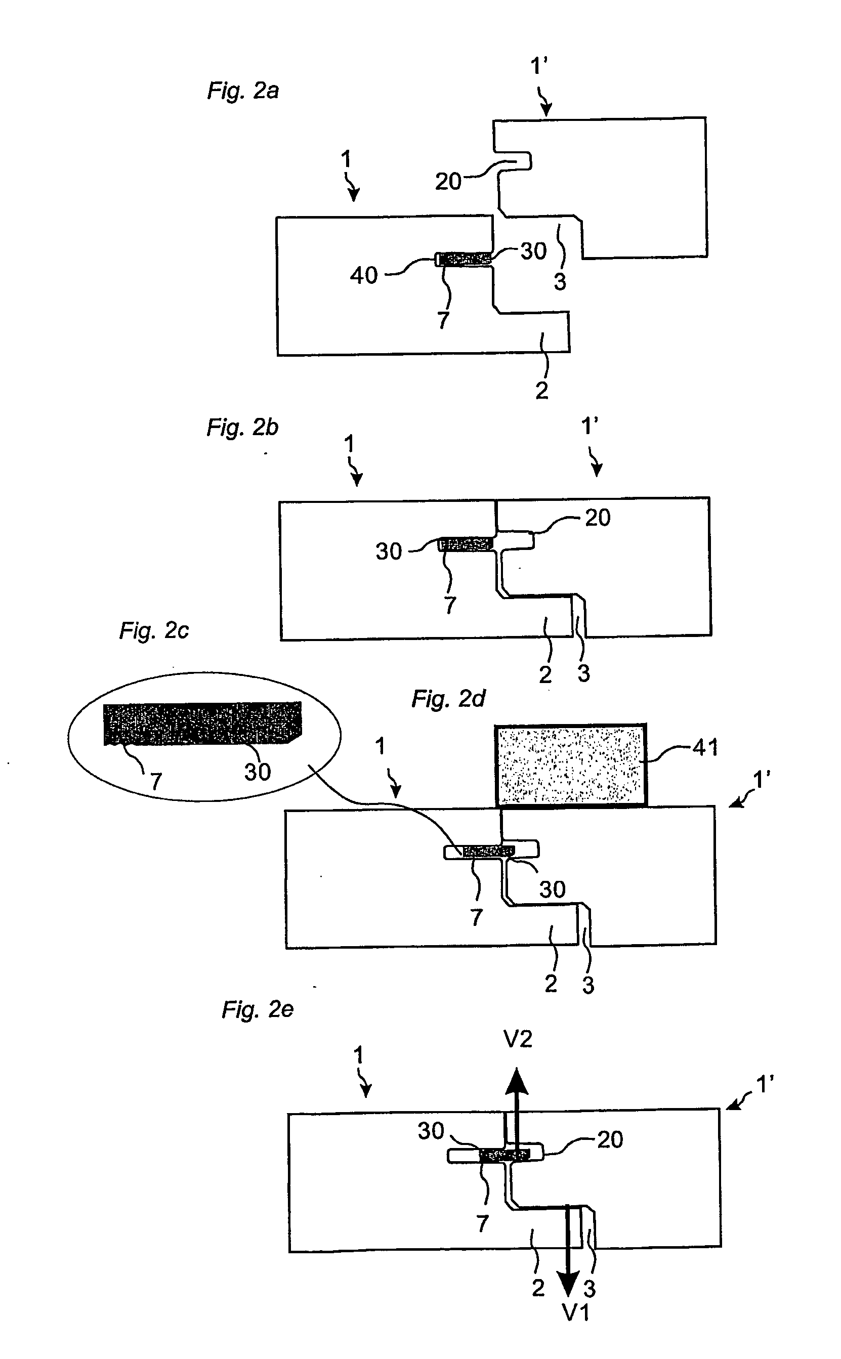
[0058]FIGS. 2a and 2b shows one embodiment of panels 1, 1′ with a magnetic locking system according to the invention. The locking system is in this embodiment of the invention used to lock two edges vertically V1, V2. A first panel 1 has a displaceable tongue 30 of magnetic material arranged in a displacement groove 40 formed in the edge of the first panel 1. The second panel 1′ comprises a tongue groove 20. The panels comprise a protruding locking strip 2 in one edge that cooperates with a cavity 3 in an adjacent edge and locks the edges in a first vertical direction V1 when the second panel 1′ is moved preferably vertically along a vertical plane VP and arranged in the same plane as the first floor panel 1. FIG. 2d shows that the magnetic tongue 30 is displaced horizontally into the tongue groove 20 when a magnet 41 is arranged on the floor surface, preferably essentially on the surface of the second panel 1′. The whole tongue 30 is displaced in the displacement groove. The tongue...


PUM


Abstract

Floor panels (1, 1′) are shown, which are provided with a mechanical locking system having a tongue (30) of magnetic material that could be locked vertically by a magnetic field.

Description

AREA OF INVENTION[0001]The invention generally relates to the field of floor panels with mechanical locking systems comprising a separate displaceable tongue allowing easy installation. The invention provides new improved locking systems and methods to install and disconnect building panels, especially floor panels and methods to produce the locking system.BACKGROUND OF THE INVENTION[0002]In particular, yet not restrictive manner, the invention concerns a mechanical locking system for rectangular floor panels with long and short edges. It should be emphasized that long and short edges are only used to simplify the description. The panels could also be square, they could have more than 4 edges and the adjacent edges could have angles other than 90 degrees. However, the invention is as well applicable to building panels in general. More particularly the invention relates mainly to the type of mechanically locking systems, which allow that angling of long edges and vertical movement of...

Claims


Application Information

Patent Timeline
IPC IPC(8): E04B5/00E04B1/38E04C2/38
CPCE04F15/02E04F15/04E04F21/22E04F2201/0138E04F2201/0153Y10T428/167E04F2201/0541E04F2201/0547E04F15/02038Y10S52/04E04F2201/0523E04F2201/06
Inventor PERVAN, DARKOPETERSON, JAN
Owner VÄLINGE INNOVATION AB
Why Eureka
Try Eureka