Image-acquisition apparatus
a technology of image acquisition and image signal, which is applied in the field of image acquisition apparatus and imageprocessing apparatus, can solve the problems of unbalanced image signal impression, inability to accurately estimate the amount of noise, and inability to generate a sense of unnaturalness in the entire image signal, so as to improve the flexibility of processing, the effect of adjusting the processing speed and changing the size of the prescribed area
- Summary
- Abstract
- Description
- Claims
- Application Information
AI Technical Summary
Benefits of technology
Problems solved by technology
Method used
Image
Examples
first embodiment
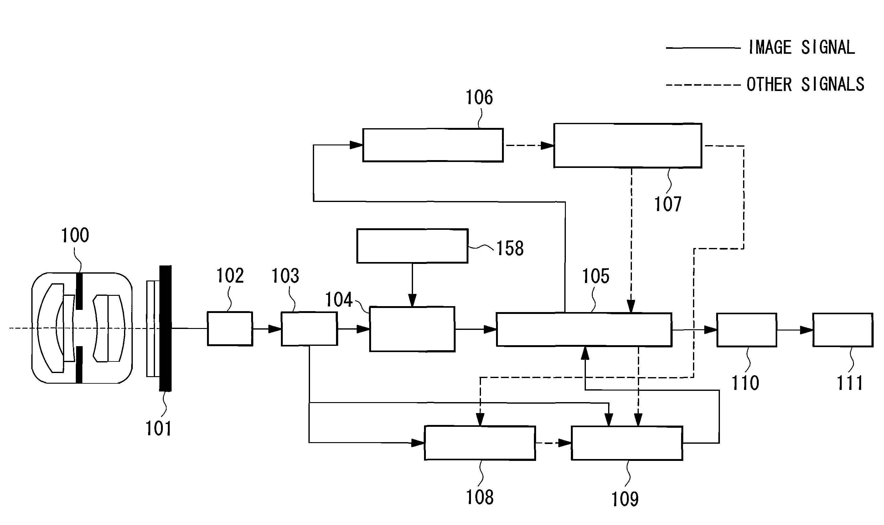
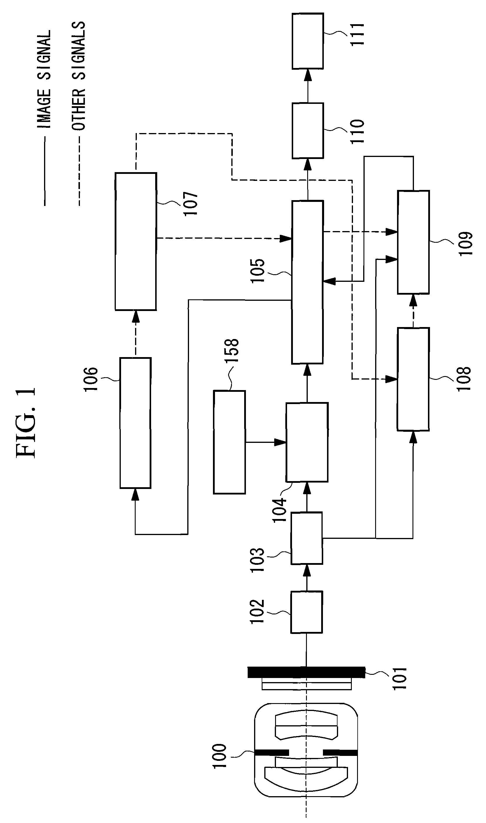
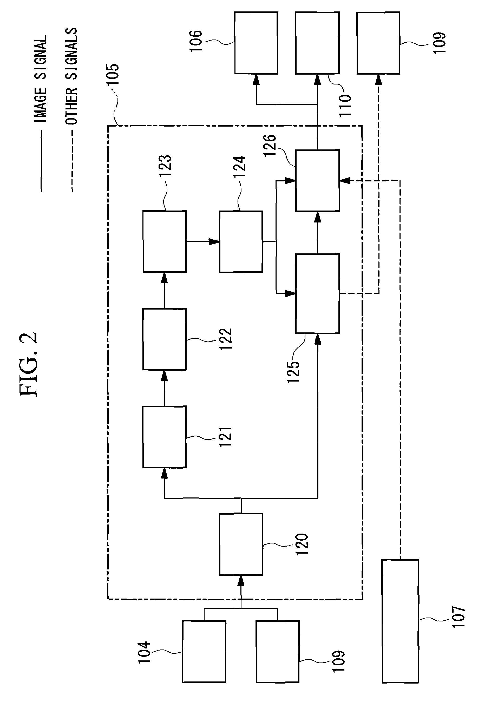
[0171]FIG. 1 is a block diagram of an example configuration of an image-acquisition apparatus according to a first embodiment of the present invention. In FIG. 1, a lens system 100 and a CCD 101 are disposed in this order along the optical axis. The CCD 101 is connected to an A / D converter 102. The A / D converter 102 is connected to a buffer 103. The buffer 103 is connected to a reduced-image creating unit 104, a noise estimating unit 108, and a noise reducing unit 109. A reduction-ratio setting unit 158 is connected to the reduced-image creating unit 104. The reduced-image creating unit 104 is connected to a signal processing unit 105. The signal processing unit 105 is connected to a correction-coefficient calculation unit 106, the noise reducing unit 109, and a compressing unit 110. The correction-coefficient calculation unit 106 is connected to a correction-coefficient map buffer 107. The correction-coefficient map buffer 107 is connected to the signal processing unit 105 and the ...
second embodiment
[0243]Next, an image-acquisition apparatus according to a second embodiment of the present invention will be described with reference to the drawings.
[0244]FIG. 18 is a block diagram of the overall structure of the image-acquisition apparatus according to the second embodiment of the present invention.
[0245]The second embodiment has substantially the same structure as the above-described first embodiment. However, the second embodiment differs from the first embodiment in that a signal processing unit 200 is included instead of the signal processing unit 105, a noise estimating unit 208 is included instead of the noise estimating unit 108, a noise reducing unit 209 is included instead of the noise reducing unit 109, and a correction-coefficient multiplication unit 201 is further included.
[0246]Features of the image-processing apparatus according to this embodiment that are the same as those according to the first embodiment will not be described, and mainly differences will be descr...
third embodiment
[0275]Next, an image-acquisition apparatus according to a third embodiment of the present invention will be described with reference to the drawings.
[0276]FIG. 25 is a block diagram of the overall structure of the image-acquisition apparatus according to the third embodiment of the present invention.
[0277]Features of the image-acquisition apparatus according to this embodiment that are the same as those according to the first embodiment will not be described, and mainly differences will be described below. Components that are the same as those according to the first embodiment are represented by the same names and reference numerals.
[0278]In FIG. 25, the signal processing unit 105 is connected to the reduced-image creating unit 104, the noise estimating unit 208, and the noise reducing unit 209. The reduction-ratio setting unit 158 is connected to the reduced-image creating unit 104. The reduced-image creating unit 104 is connected to the correction-coefficient calculation unit 106....
PUM
 Abstract
Description
Claims
Application Information
 - R&D
- Intellectual Property
- Life Sciences
- Materials
- Tech Scout
- Unparalleled Data Quality
- Higher Quality Content
- 60% Fewer Hallucinations
Browse by: Latest US Patents, China's latest patents, Technical Efficacy Thesaurus, Application Domain, Technology Topic, Popular Technical Reports.
© 2025 PatSnap. All rights reserved.Legal|Privacy policy|Modern Slavery Act Transparency Statement|Sitemap|About US| Contact US: help@patsnap.com


