Supercharge Your Innovation With Domain-Expert AI Agents!

X-ray tube target brazed emission layer

a technology of emission layer and x-ray tube, which is applied in the manufacture of x-ray tube targets, x-ray tube convertors, electrode systems, etc., can solve the problems of high peak temperature occurring in the target assembly, life and reliability problems with respect to the targ

Inactive Publication Date: 2012-02-14
GENERAL ELECTRIC CO
View PDF31 Cites 9 Cited by
  • Summary
  • Abstract
  • Description
  • Claims
  • Application Information

AI Technical Summary

Problems solved by technology

Higher peak power, though, results in higher peak temperatures occurring in the target assembly, particularly at the target “track,” or the point of impact on the target.
Thus, for increased peak power applied, there are life and reliability issues with respect to the target.

Method used


Image

  • X-ray tube target brazed emission layer
  • X-ray tube target brazed emission layer
  • X-ray tube target brazed emission layer

Examples


Embodiment Construction

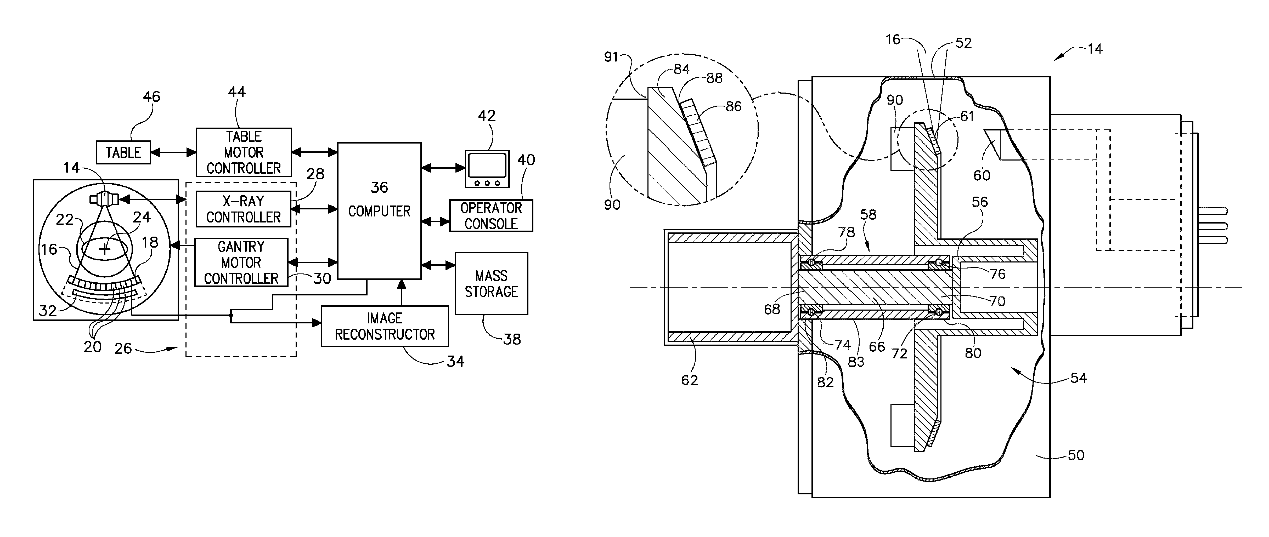
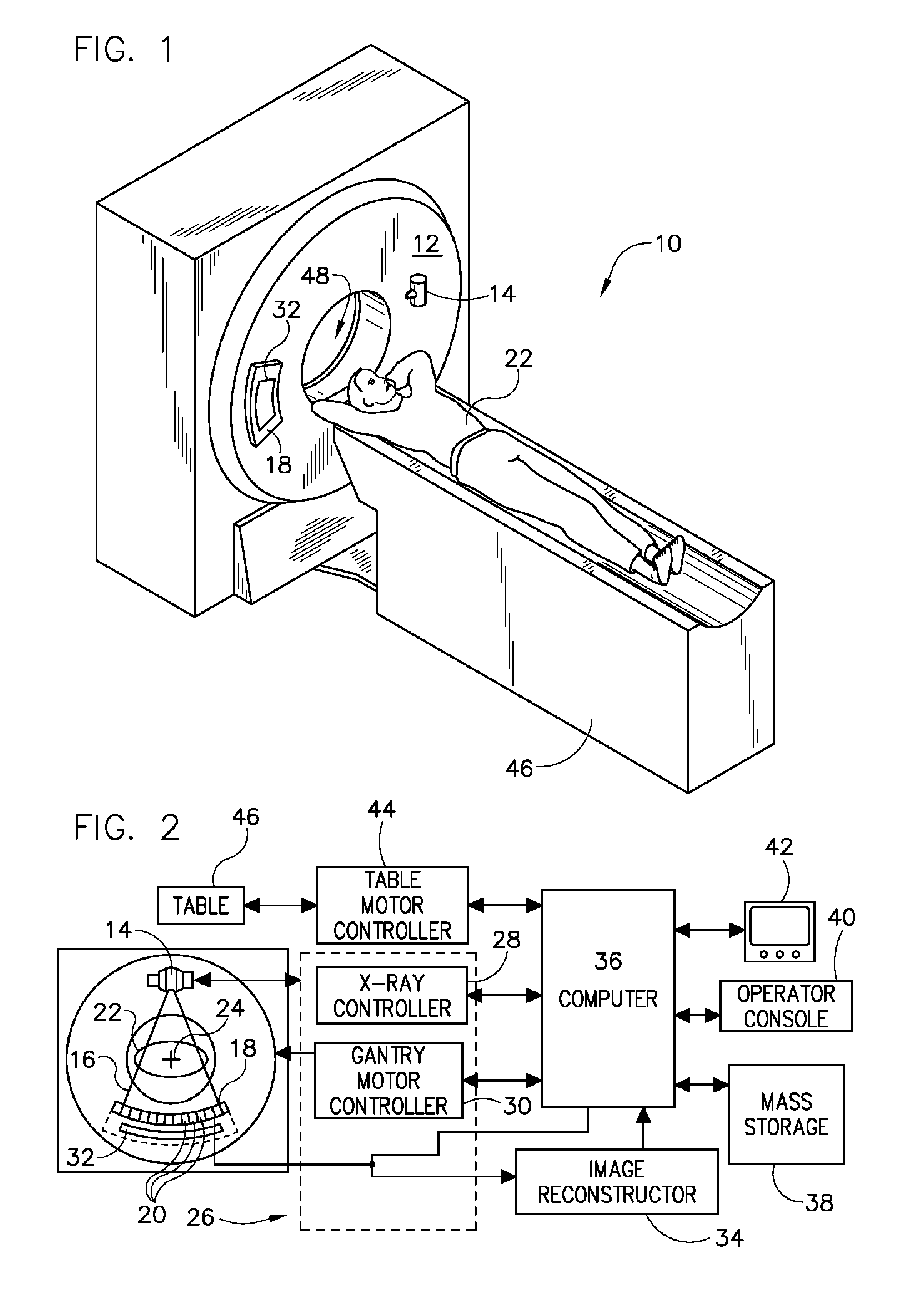
[0018]The operating environment of the present invention is described with respect to the use of an x-ray tube as used in a computed tomography (CT) system such as, for instance, a sixty-four slice CT system. The present invention will be described with respect to a “third generation” CT medical imaging scanner, but is equally applicable with other CT systems, such as a baggage scanner. However, it will be appreciated by those skilled in the art that the present invention is equally applicable for use in other systems that require the use of an x-ray tube. Such uses include, but are not limited to, x-ray imaging systems (for medical and non-medical use), mammography imaging systems, and RAD systems.

[0019]Moreover, the present invention will be described with respect to use in an x-ray tube. However, one skilled in the art will further appreciate that the present invention is equally applicable for other systems that require operation of a target used for the production of x-rays whe...


PUM


Abstract

A target for generating x-rays includes a target substrate comprising at least one layer of a target material, a track comprising at least one layer of a track material, the track configured to generate x-rays from high-energy electrons impinging thereon, and a braze joint attaching the target substrate to the track.

Description

BACKGROUND OF THE INVENTION[0001]The present invention relates generally to x-ray tubes and, more particularly, to a method and apparatus of fabricating a target for x-ray generation.[0002]X-ray systems typically include an x-ray tube, a detector, and a bearing assembly to support the x-ray tube and the detector. In operation, an imaging table, on which an object is positioned, is located between the x-ray tube and the detector. The x-ray tube typically emits radiation, such as x-rays, toward the object. The radiation typically passes through the object on the imaging table and impinges on the detector. As radiation passes through the object, internal structures of the object cause spatial variances in the radiation received at the detector. The detector then emits data received, and the system translates the radiation variances into an image, which may be used to evaluate the internal structure of the object. One skilled in the art will recognize that the object may include, but is...

Claims


Application Information

Patent Timeline
Patent Type & Authority Patents(United States)
IPC IPC(8): H01J35/10H01J35/08
CPCH01J35/10H01J2235/083
Inventor STEINLAGE, GREGORY ALANHEBERT, MICHAEL
Owner GENERAL ELECTRIC CO
Features
  • R&D
  • Intellectual Property
  • Life Sciences
  • Materials
  • Tech Scout
  • Unparalleled Data Quality
  • Higher Quality Content
  • 60% Fewer Hallucinations
Learn More