Follower vehicle control system and method for forward and reverse convoy movement

a control system and follower technology, applied in process and machine control, instruments, navigation instruments, etc., can solve the problems of insufficient speed of position update frequency of most gps systems, inability to quickly respond to the situation, and inability to use gps systems around large buildings

Active Publication Date: 2012-02-14
AUTONOMOUS SOLUTIONS
View PDF4 Cites 49 Cited by
  • Summary
  • Abstract
  • Description
  • Claims
  • Application Information

AI Technical Summary

Problems solved by technology

Unfortunately, however, GPS receives require a direct view or “line-of-sight” access to at least three, and typically more, GPS satellites.
This direct view or line-of-sight limitation typically prevents GPS systems from being used around large buildings (e.g., in urban areas), in tunnels, or underground.
Furthermore, the position update frequency of most GPS systems is not rapid enough to allow for fast traveling where the convoy vehicles are close and rapid response times are required.
This system has limited utility in that it can only be used where magnet markers are present.
However, the data received from the camera is too large and cumbersome for use at high speeds.
Another drawback is that the leader vehicle must always be in the line of sight of the camera.

Method used


Image

  • Follower vehicle control system and method for forward and reverse convoy movement
  • Follower vehicle control system and method for forward and reverse convoy movement
  • Follower vehicle control system and method for forward and reverse convoy movement

Examples


Embodiment Construction

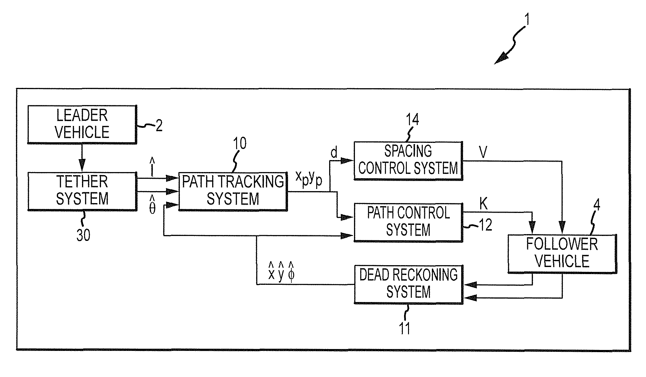
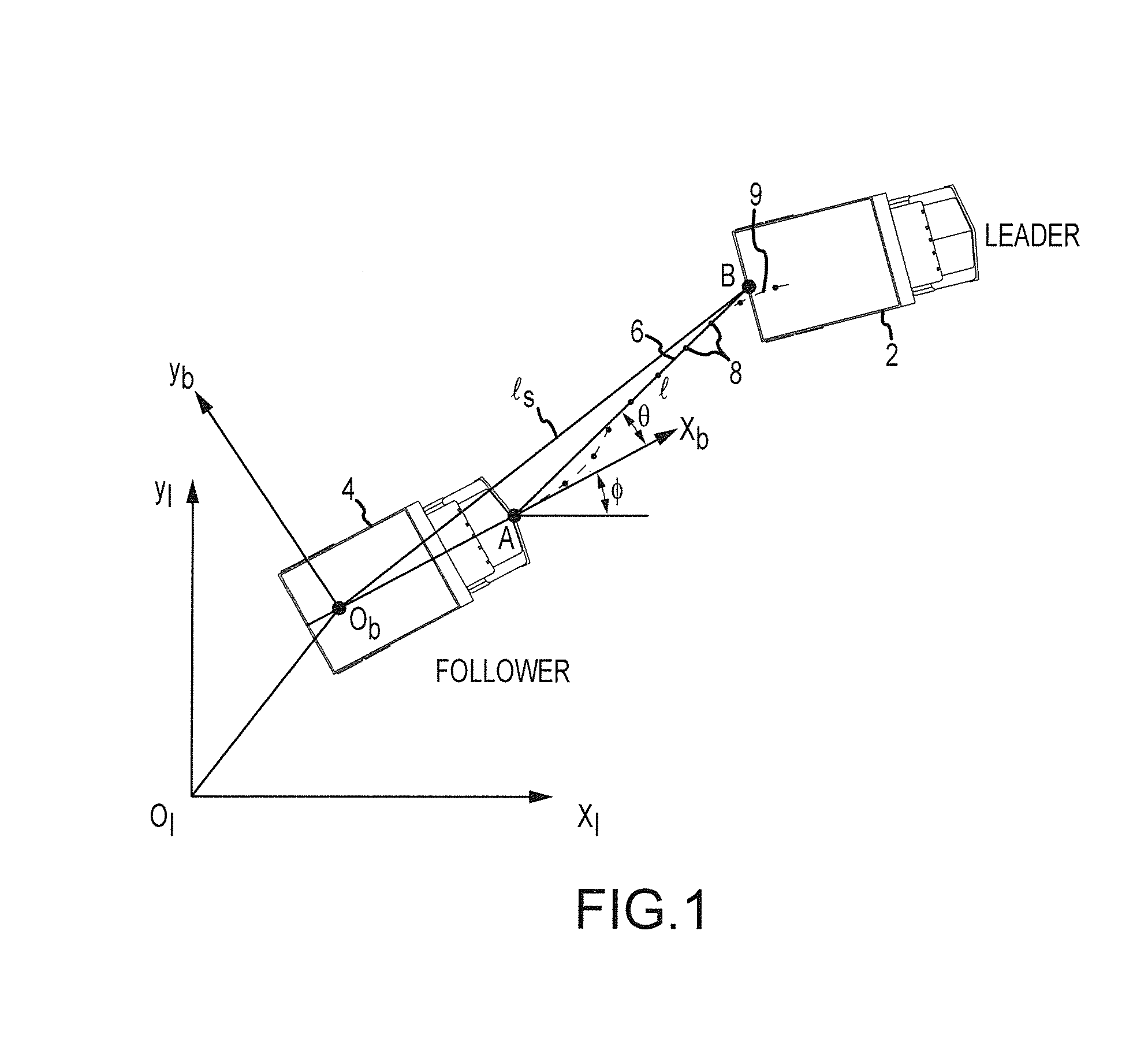
[0025]One embodiment of a vehicle control system 1 for causing a follower vehicle 4 to follow a leader 2 is best seen in FIGS. 1-5 and may comprise a tether system 30 that is mounted to the follower vehicle 4. Tether system 30 includes a tether 6 having an end that is adapted to be attached to the leader 2, e.g., at point “B” of leader 2. A length sensor 36 (FIG. 5) operatively associated with tether system 30 senses a length l of tether 6 that extends between leader 2 and follower vehicle 4 (e.g., between points “A” and “B”), as best seen in FIG. 1. Tether system 30 also includes an angle sensor 40 (FIG. 5) that senses an angle θ between tether 6 and the follower vehicle 4, as also best seen in FIG. 1.

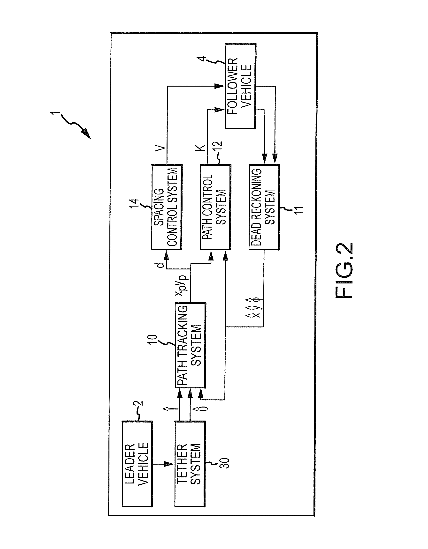
[0026]A path tracking system 10 (FIGS. 2 and 3) operatively associated with the tether system 30 receives from the tether system 30 information about the length l of tether 6 and the angle θ that tether 6 makes with respect to follower vehicle 4. Path tracking system 10 uses the tethe...


PUM


Abstract

A vehicle control system for causing a follower vehicle to follow a leader may have a tether system mounted to the follower vehicle. The tether system may include a tether having an end adapted to be attached to the leader, a length sensor, and an angle sensor. A path tracking system operatively associated with the tether system determines a path traveled by the leader. A path control system operatively associated with the path tracking system and the follower vehicle causes the follower vehicle to follow the path traveled by the leader. A spacing control system operatively associated with the path tracking system and the follower vehicle causes the follower vehicle to maintain a predetermined spacing between the follower vehicle and the leader.

Description

REFERENCE TO CO-PENDING PROVISIONAL APPLICATIONS[0001]Applicants hereby claim the benefit of earlier filed co-pending provisional applications, Application No. 61 / 189,527, filed on Aug. 20, 2008, and Application No. 61 / 091,273, filed Aug. 22, 2008, both of which are specifically incorporated herein by reference for all that they disclose.TECHNICAL FIELD[0002]This invention relates to vehicle control systems in general and more specifically to control systems for vehicle convoys.BACKGROUND[0003]A convoy can be used to transport large quantities of items to a certain destination in order to reduce the amount of time and number of return trips required, provide support for vehicles in order to attain safe travel, and can also be used to reduce traffic congestion on roadways. A robotic convoy can be used to further the efficiency of convoy missions in many different areas.[0004]The robotic convoy concept can be used with many different types of robotic vehicles. In its simplest form, th...

Claims


Application Information

Patent Timeline
Patent Type & Authority Patents(United States)
IPC IPC(8): G05D1/00
CPCG05D1/0227G05D1/0293G05D1/0272G05D2201/0213G05D1/0278G05D1/0295
Inventor FERRIN, JEFFREY L.THAYN, BRETTHORNBERGER, MICHAEL
Owner AUTONOMOUS SOLUTIONS
Why Eureka
Try Eureka