Horizontal concrete saw attachment

Active Publication Date: 2012-02-21
THE JOHN T SHERMENT TRUST
View PDF15 Cites 25 Cited by
  • Summary
  • Abstract
  • Description
  • Claims
  • Application Information

AI Technical Summary

Benefits of technology

[0007]The frame of the attachment supports a gear box. A gear box pulley for supplying power to the gear box from the saw extends from the side of the gear box. A drive belt extends around both the gear box pulley that powers the gear box and around a power pulley provided on the saw that was the original power source for rotating the now removed horizontal shaft and vertical saw blade. For safety purposes, a removable shroud covers portions of the attachment to prevent injury to the operator from contact with moving parts when the saw is being operated.
[0008]The gear box has a drive shaft extending vertically downward out of the gear box. A horizontal saw blade can be removably attached to the drive shaft via blade bolts that extend through the blade and engage threaded openings provided on the drive shaft so that the saw can be used for making horizontal cuts in concrete. Water is supplied via water hoses from the saw to both the gear box and to the horizontal saw blade as a means of cooling and lubricating these items. A water nozzle is provided on the gear box to supply water to the gear box, and a water spray bar extends above and across the entire diameter

Problems solved by technology

However, when it is necessary to make horizontal cuts in concrete, such as when a curb must be cut, the large commercial concrete saw

Method used


Image

  • Horizontal concrete saw attachment
  • Horizontal concrete saw attachment
  • Horizontal concrete saw attachment

Examples


Example

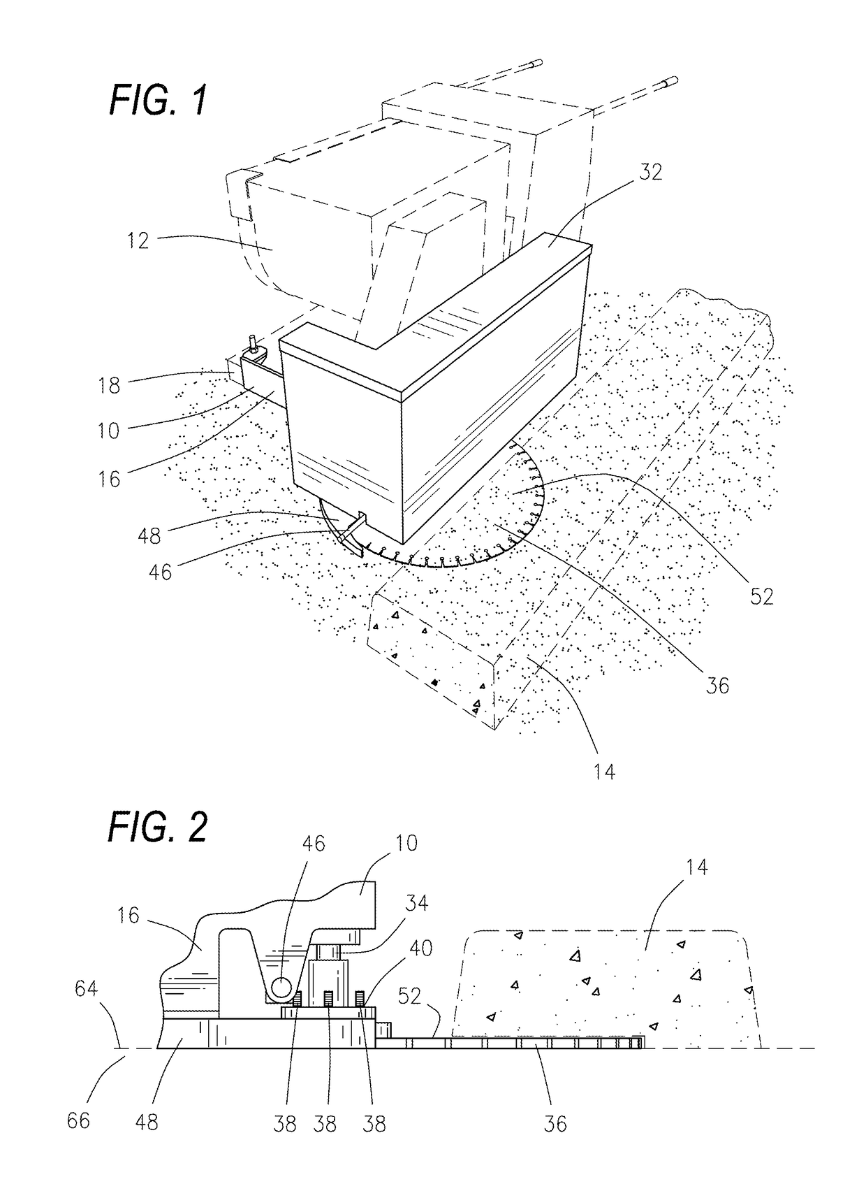
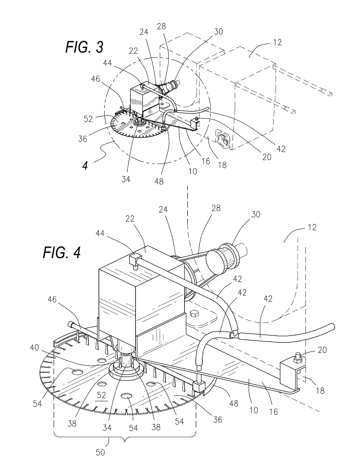
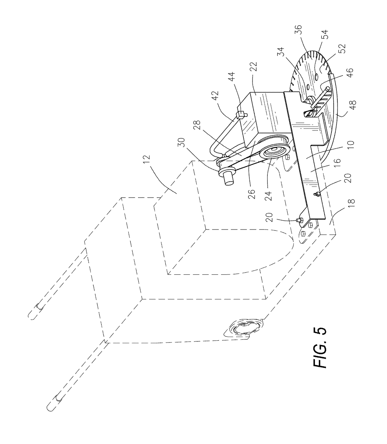
[0017]Referring now to the drawings and initially to FIGS. 1-5, there is illustrated an attachment 10 for an existing commercial concrete saw 12 to convert the saw 12 from vertically cutting to horizontally cutting. With this attachment 10, the saw 12 can be used to cut vertically oriented curbs 14 or other vertically oriented concrete structures. To use the attachment 10, the existing vertically oriented saw blade (not illustrated) and horizontal shaft (not illustrated) are first removed from the saw 12, and then a frame 16 of the attachment 10 is bolted onto the frame 18 of the saw 12. The frame 16 of the attachment 10 has adjustment bolts 20 for making slight adjustments in the vertical and lateral position of the attachment 10 relative to the saw 12.

[0018]As illustrated in FIGS. 3-5, the frame 16 of the attachment 10 supports a gear box 22. A gear box pulley 24 for supplying power to the gear box 22 from the saw 12 extends from the side 26 of the gear box 22. A drive belt 28 ext...


PUM

PropertyMeasurementUnit
Poweraaaaaaaaaa
Flow rateaaaaaaaaaa

Abstract

An attachment for an existing commercial concrete saw to convert the vertically cutting saw to a horizontally cutting saw. The saw's vertically oriented saw blade and associated horizontal shaft are first removed and the attachment is installed on the saw. The attachment has a gear box with pulley for receiving power from a pulley on the saw via a drive belt that extends around both pulleys. The gear box has a drive shaft extending vertically downward out of the gear box. Either a horizontal saw blade or cup brush can be removably attached to the drive shaft so that the saw can be used for making horizontal cuts in concrete or alternately the cup brush can be used to remove striping off the surface of a road. The gear box and the horizontal saw blade or cup brush are water cooled and lubricated.

Description

BACKGROUND OF THE INVENTION[0001]1. Field of the Invention[0002]The present invention is an attachment for an existing commercial concrete saw to convert the vertically cutting saw to a horizontally cutting saw. To install this attachment, the existing vertically oriented saw blade and horizontal shaft are removed and the attachment is installed on the saw. The attachment has a gear box with a gear box pulley for receiving power from a power pulley provided on the saw via a drive belt that extends around both pulleys. The gear box has a drive shaft extending vertically downward out of the gear box. A horizontal saw blade can be removably attached to the drive shaft so that the saw can be used for making horizontal cuts in concrete. Alternately a cup brush can be attached to the drive shaft so that the saw can be used to remove striping off the surface of a road. Both the gear box and the saw blade or cup brush are water cooled and lubricated.[0003]2. Description of the Related Art[0...

Claims


Application Information

Patent Timeline
IPC IPC(8): B28D1/04
CPCB28D1/046
Inventor SHERMENT, JOHN T.
Owner THE JOHN T SHERMENT TRUST
Why Eureka
Try Eureka