Ball catcher with retention capability

a technology of ball catcher and capacity, which is applied in the direction of fluid removal, sealing/packing, and wellbore/well accessories, etc., can solve the problems of preventing subsequent operations, affecting the efficiency of the catcher, and the feature can be less than ideal, so as to maximize the number of balls, increase the differential pressure, and maximize the effect of the annular spa

Active Publication Date: 2012-02-21
BAKER HUGHES INC
View PDF10 Cites 12 Cited by
  • Summary
  • Abstract
  • Description
  • Claims
  • Application Information

AI Technical Summary

Benefits of technology

[0006]A ball catcher is designed to stop balls that are the same size or different sizes at an inlet on a seat that is connected to a movable biased sleeve. Once the ball or other shaped object lands at the seat the flow around it increases differential pressure on the seat and sleeve and displaces them against the bias. The ball goes into a surrounding annular space and cannot exit. A preferably spiral sleeve guide the movement of the balls in the annular space so that efficient use of the annular space is made to maximize the number of balls that can be captured per unit length of the annular space. As soon as the ball enters the annular space the sleeve shifts back to the original position to stop the next ball at the inlet. Once in the annular space, the balls cannot escape if there is a flow reversal. The central passage remains open to pass other tools and flow.

Problems solved by technology

This design left the central passage obstructed which hampered or prevented subsequent operations further downhole from the Catcher Sub.
There are several issues with this design.
First, if there is a flow reversal it will force the balls uphole and out of the ball catcher.
Second, the way this ball catcher is set up with parallel bores, it has to have the channel between the bores because it has no way to insure the small balls will go in the pass through passage 28.
Another disadvantage is that it has a pass through passage for one size of ball as opposed to catching all balls that enter.
While it is recognized that the latter may simply be a design objective when a ball catcher is applied to a specific tubular string, it is recognized that in other applications, this feature can be less than ideal.

Method used


Image

  • Ball catcher with retention capability

Examples


Embodiment Construction

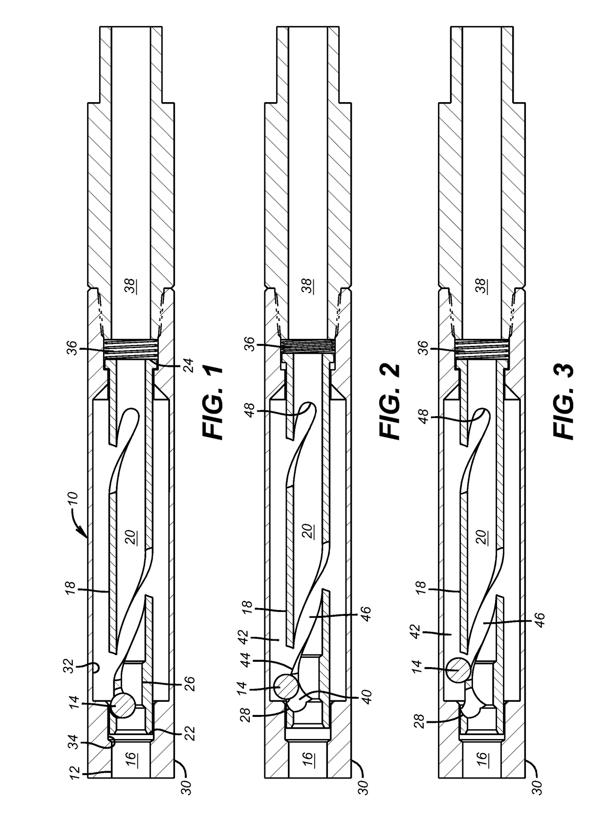
[0010]The ball catcher 10 has an inlet 12 connected to a tubing string that is not shown. When the ball 14 passes through a ball seat (not shown) that is uphole it continues into inlet passage 16. A movable sleeve 18 has a passage 20 that extends from end 22 at the uphole end to end 24 at the downhole end. Toward the uphole end 22 the passage 20 has a reduced diameter section 26. Adjacent the reduced diameter section 26 is a lateral passage or exit 28 that is best seen in FIGS. 2 and 3 after the ball 14 has gone past. In the FIG. 1 position the housing 30 has a radial surface 32 and a cylindrical surface 34 adjacent and in an uphole direction. The ball 14 goes into the upper end 22 and cannot progress further down passage 20 because of reduced diameter section 26. There is enough room around the ball 14 when it engages reduced diameter section 26 to be pushed laterally against the lateral passage 28. This is the FIG. 1 position. Since the flow continues from inlet passage 16 a press...


PUM


Abstract

A ball catcher is designed to stop balls that are the same size or different sizes at an inlet on a seat that is connected to a movable biased sleeve. Once the ball or other shaped object lands at the seat the flow around it increases differential pressure on the seat and sleeve and displaces them against the bias. The ball goes into a surrounding annular space and cannot exit. A preferably spiral sleeve guide the movement of the balls in the annular space so that efficient use of the annular space is made to maximize the number of balls that can be captured per unit length of the annular space. As soon as the ball enters the annular space the sleeve shifts back to the original position to stop the next ball at the inlet. Once in the annular space, the balls cannot escape if there is a flow reversal. The central passage remains open to pass other tools and flow.

Description

FIELD OF THE INVENTION[0001]The field of this invention is devices used in tubular strings to catch and retain objects previously dropped against a seat to operate a downhole tool and later ejected from the seat. More specifically, the present invention captures the ejected objects and preferably retains them outside a main bore regardless of the flow direction in the string.BACKGROUND OF THE INVENTION[0002]A tubular string extending downhole can have a plurality of seats that accept objects, usually spheres, which land on discrete seats so that pressure can be built up and a downhole tool in that string operated. The balls can be the same or different sizes as are the corresponding seats. Regardless of the configuration it is desirable after operating the downhole tool to eject the ball from a given seat by a variety of known techniques and then to capture the balls. The reason capturing the balls is a benefit is that if left in the tubular string and there is a reversal in flow di...

Claims


Application Information

Patent Timeline
Patent Type & Authority Patents(United States)
IPC IPC(8): E21B34/06
CPCE21B23/04E21B34/142
Inventor NELSON, JONATHAN F.HERN, GREGORY L.
Owner BAKER HUGHES INC
Why Eureka
Try Eureka