
Focusing device, image pick-up apparatus, and control method

a technology of focusing device and image pickup, which is applied in the direction of camera focusing arrangement, printers, instruments, etc., can solve the problems of inability to obtain sufficient accurate results by metering, the difference between the speed of driving the focusing lens in the tv-af process and the speed of the phase detection process, and the inability to accurately measure the distance of objects, etc., to achieve the effect of reducing user discomfor

Inactive Publication Date: 2012-02-21
CANON KK
View PDF13 Cites 4 Cited by
  • Summary
  • Abstract
  • Description
  • Claims
  • Application Information

AI Technical Summary

Benefits of technology

[0013]The present invention provides a focusing technique that uses a combination of a TV-AF process and a different process and that can greatly reduce user discomfort compared with known techniques.

Problems solved by technology

Unfortunately, however, when an object is present adjacent to a camera or when a contrast of an object is low, it is often impossible to meter an object distance by use of a phase difference or, even if possible, it is difficult to obtain sufficiently accurate results by metering.
Therefore, for a combined use of the TV-AF process and the phase detection process, the difference between the speed of driving the focusing lens in the TV-AF process and that in the phase detection process may be undesirably large depending on the state of the object.

Method used


Image

  • Focusing device, image pick-up apparatus, and control method
  • Focusing device, image pick-up apparatus, and control method
  • Focusing device, image pick-up apparatus, and control method

Examples


first exemplary embodiment

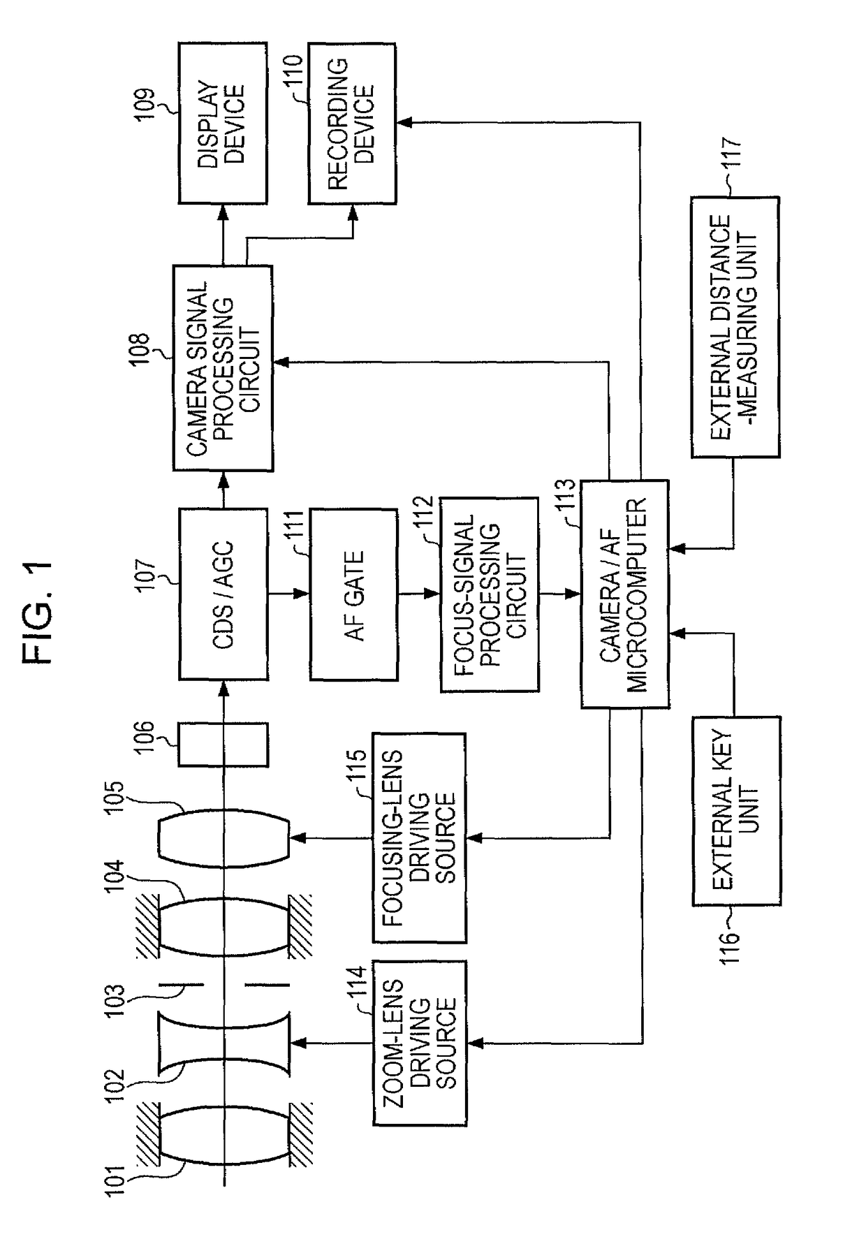
[0030]FIG. 1 is a block diagram of an image pick-up apparatus according to the present embodiment. Referring to FIG. 1, a first lens unit 101 is fixed, a zoom lens 102 functions to vary magnification, an aperture stop 103 functions as an aperture stop, and a second lens unit 104 is fixed. A focus compensation lens 105 functions both to correct movement of a focal plane caused by zooming and to perform focusing (hereinafter referred to as focusing lens). An image pick-up element 106 can be, for example, a CCD or a CMOS. A CDS / AGC / AD converter 107 samples an output of the image pick-up element 106, performs gain control thereon, and converts the output to digital form. A camera signal processing circuit 108 processes an output signal from the CDS / AGC / AD converter 107 and then generates an image signal. A display device 109 displays an output signal from the camera signal processing circuit 108 and allows a user to monitor an image. A recording device 110 records information by using m...

second exemplary embodiment

[0068]A second embodiment will now be described. The system configuration of an image pick-up apparatus is illustrated in the block diagram of the same FIG. 1 as in the first embodiment. Hereinafter, the description of the same components as in the first embodiment is omitted.

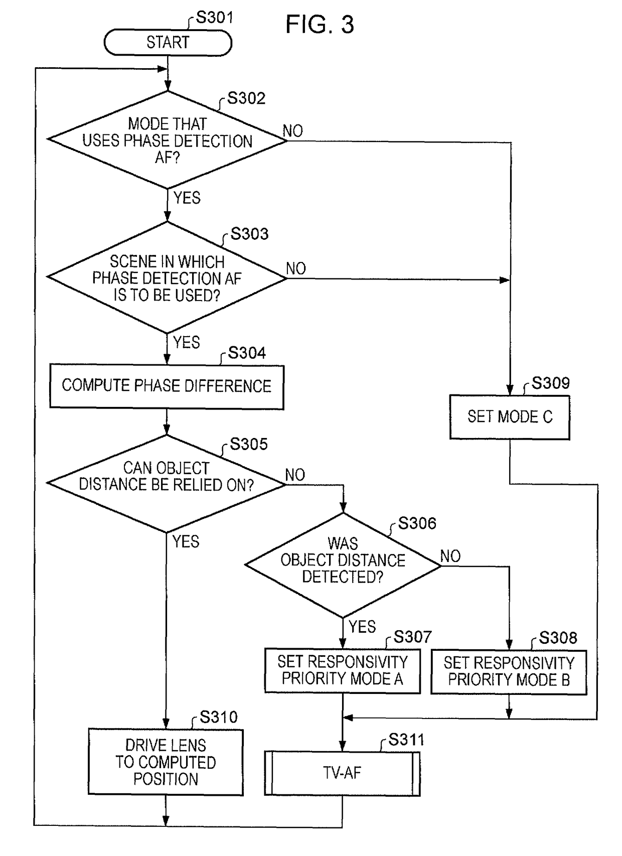
[0069]An overview of a focusing control performed in the camera / AF microcomputer 113 will be described with reference to FIG. 9. FIG. 9 corresponds to FIG. 3, which is described in the first embodiment. Steps S301 through S304 and S309 through S311 are similar to those from FIG. 3, and therefore description of the same will not be repeated.

[0070]In step S905, it is determined whether the accuracy of the object distance computed in step S304 can be relied on and the computed object distance can be used in driving the focusing lens 105. If it is determined that the object distance can be used in driving the focusing lens 105, flow proceeds to step S310; otherwise flow proceeds to step S906. In step S906, the driv...


PUM


Abstract

A focusing device includes a first focus-position determining unit configured to determine a focus position based on a change in a radio-frequency component in an image signal obtained with movement of a focusing lens, a second focus-position determining unit configured to determine a focus position by using a different process from a process performed by the first focus-position determining unit, a mode setting unit configured to select at least a first mode which uses a result with the first focusing-position determining unit together with the second focusing-position determining unit or a second mode which uses a result with the first focus-position determining unit without the second focus-position determining unit, and a control unit configured to control driving of the focusing lens according to selection by the mode setting unit such that the focusing lens is driven in the first mode at a higher speed than in the second mode.

Description

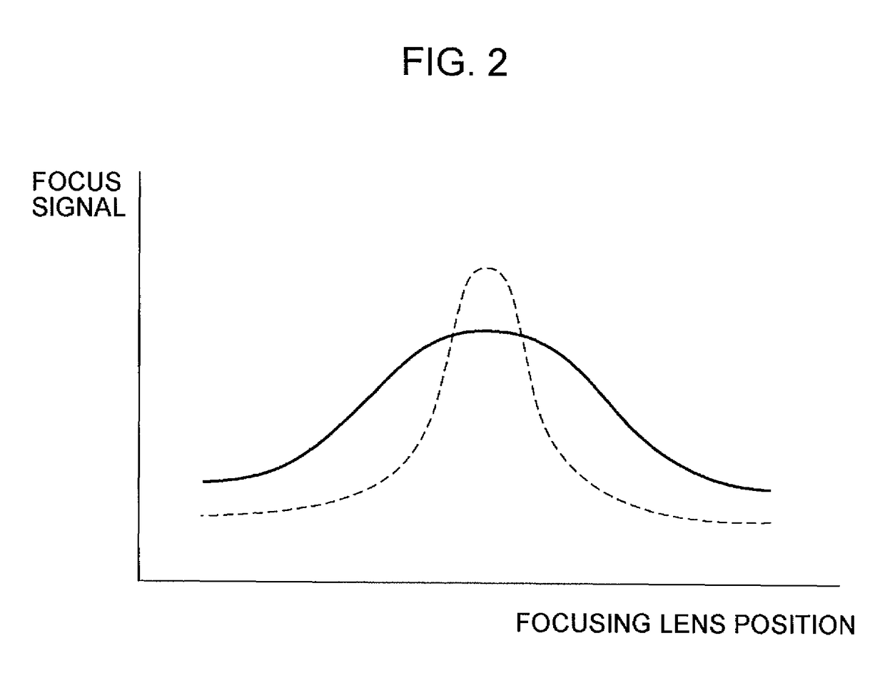
BACKGROUND OF THE INVENTION[0001]1. Field of the Invention[0002]The present invention relates to a focusing technique for use in an image pick-up apparatus.[0003]2. Description of the Related Art[0004]Some image pick-up apparatuses, such as video cameras, use an auto focus control achieved by detecting a focus signal representing the sharpness of a screen from an image signal obtained by photoelectrically converting an object image by use of an image pick-up element, such as a charge-coupled device (CCD) or a complementary mental-oxide semiconductor device (CMOS). This control is an AF system that controls the position of a focusing lens so as to maximize the level of a focus signal (hereinafter referred to sometimes as a TV-AF process).[0005]A focus signal used in the TV-AF process generally employs a radio-frequency component of an image signal extracted by a band-pass filter for a certain band. For a normal object image, as illustrated in a graph of FIG. 2, where the horizontal a...

Claims


Application Information

Patent Timeline
Patent Type & Authority Patents(United States)
IPC IPC(8): G03B3/10
CPCG02B7/102G02B7/36G03B13/36
Inventor KAWANISHI, ATSUYA
Owner CANON KK
Learn More