Soft start circuitry for LED lighting devices with simultaneous dimming capability

a technology of led lighting and soft start circuitry, which is applied in the direction of semiconductor devices for light sources, lighting and heating apparatus, electroluminescent light sources, etc., can solve the problems of reducing the supply voltage available to other circuits, affecting the life of led(s), and affecting the safety of users, etc., to achieve convenient handling and installation, prolong the life of led(s), and reduce user discomfort.

Active Publication Date: 2019-08-20
HEARTLAND INC
View PDF12 Cites 0 Cited by
  • Summary
  • Abstract
  • Description
  • Claims
  • Application Information

AI Technical Summary

Benefits of technology

[0021]A first object of the invention is to enable an LED light to be soft started to both prolong the life of the LED(s) and to reduce user discomfort. A second object of the invention is to provide automated soft start of the LED(s) without the inconvenience of manual intervention. Another object of the present invention is to enable field installation of necessary electrical components to achieve automated soft start of the LED(s). A further object of the invention is to provide a safe, compact, and easily handled and installed apparatus that provides an installer clear visual direction for intuitive installation. Yet another object of the present invention is to enable visual identification of internal failure for ready troubleshooting.

Problems solved by technology

The effect of significant inrush current can be highly detrimental to many different electrical components and circuits, including not only the components directly receiving the elevated inrush current, but also downstream components or separate devices sharing a common power line with the directly affected components.
Inrush currents can damage device components, lower supply voltage available to other circuits, decrease power efficiency, cause system errors, make devices difficult to control, and complicate device design.
For example, if the input power source for a device is current limited or has poor load regulation, large inrush currents can cause the input voltage to drop significantly, thereby affecting overall device operation.
While many devices are subject to problematic inrush currents, DC-to-DC converters and power amplifiers are particularly susceptible because of input capacitors and / or filter element charging that occurs when power is first provided to such devices.
One of these issues is the starting and illuminating of the LEDs.
Even when a power supply has been designed to start up and reach stable power levels prior to powering one or more LEDs, the LEDs will also undergo a significant and sudden heating when power is initially applied.
This sudden heating may not alter the inrush current in a well-designed power supply, but it will nevertheless affect the reliability of the LED or bank of LEDs.
Sudden heating will in most materials lead to sudden thermal expansion.
If the materials are not sufficiently malleable, this expansion can cause devices including LEDs to fracture and break, thereby resulting in catastrophic failure of the LED.
In the case of an LED is coupled securely to a heat sink, sudden heating within the LED may not only increase the risk of damage to the LED, but it will also lead to sudden differential thermal expansion at the junction between the LED and the heat sink or bond pads.
In other words, the LED may get quite hot and expand before the heat sink or bond pad even warms up.
This can cause the LED to separate from the heat sink or bond pad, depriving the LED of vital cooling or electrically disconnecting the LED, in either case eventually leading to failure.
As we all know, a very sudden transition from dark to bright illumination can be quite disconcerting.
As may be appreciated, this is inconvenient, and as a result, many times when a user switches on power to the LED lights, they will do so by simply toggling a light switch, which will instantaneously energize the lights to the full intensity that they were last set to.
As described above, this can both reduce the life expectancy of the LED light and cause discomfort for those exposed to the instantaneous change in light intensity.
Unfortunately, many LED dimmers and drivers have been fabricated and installed that do not address the soft starting of the LEDs, leading to decreased reliability and greater user discomfort.
These installed driver circuits are quite complex, and heretofore could not be field modified.

Method used


Image

  • Soft start circuitry for LED lighting devices with simultaneous dimming capability
  • Soft start circuitry for LED lighting devices with simultaneous dimming capability
  • Soft start circuitry for LED lighting devices with simultaneous dimming capability

Examples


Embodiment Construction

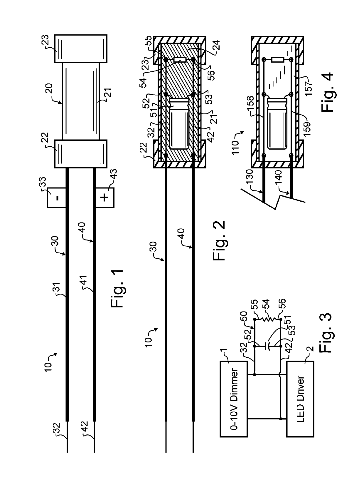
[0030]Manifested in the preferred embodiment, the present invention provides a preferred embodiment soft start circuit device 10 amenable to retrofitting existing 0-10 volt DC dimmer and LED driver circuits, to induce soft start energization of LED based lighting devices. Preferred embodiment soft start circuit device 10 provides several electrical components in a package housing 20 suitable for intuitive field installation.

[0031]Preferred embodiment soft start circuit device 10 designed in accordance with the teachings of the present invention is depicted in finished form in FIG. 1, ready for installation. A capsule 20 is constructed from a generally cylindrical packaging tube 21 and a pair of end caps 22, 23. Extending from end cap 22 are a pair of electrical wires 30, 40. Wire 30 has suitable insulation 31 encompassing all but the exposed terminal end of conductor 32. Wire 40 has suitable insulation 41 that likewise preferably encompasses all but the exposed terminal end of condu...


PUM


Abstract

A soft start circuit device couples at the junction between a 0-10 volt DC dimmer and an LED driver. A first wire couples with the positive polarity dimmer output, and a second wire couples with the negative polarity dimmer output. A capsule provides electrical insulation and physical consolidation and isolation to the capsule interior, and the first and second wires each pass through the capsule wall into the capsule interior. A capacitor and resistor are retained in the capsule interior and are each electrically coupled in parallel across the first and second wires. A sealant fills the capsule interior. At least one indicium is affixed with each wire, to indicate proper polarity connection with the 0-10 volt DC dimmer output. The capsule may further comprise a generally cylindrical and light transmissive polycarbonate packaging tube, and first and second end caps. The sealant may also comprise a light transmissive silicone sealant.

Description

CROSS REFERENCE TO RELATED APPLICATIONS[0001]The present application claims the benefit of U.S. provisional patent application 62 / 386,494 filed Dec. 3, 2015 of like title and inventorship, the teachings and entire contents which are incorporated herein by reference.BACKGROUND OF THE INVENTION1. Field of the Invention[0002]The present invention is directed generally to soft start Light Emitting Diode (LED) lighting, and more particularly to retrofitting existing commercially available circuitry to provide enhanced soft start circuitry amenable to energizing LED based lighting devices.2. Description of the Related Art[0003]Inrush current is generally a momentary current surge in an electrical device occurring when a power control device is first activated. The term is also sometimes used to refer to the maximum, instantaneous input current drawn by an electrical device when first turned on. Inrush current typically reduces to a lower steady-state current during normal device operation...

Claims


Application Information

Patent Timeline
Patent Type & Authority Patents(United States)
IPC IPC(8): H05B33/08F21V23/00F21V15/015H05B44/00F21Y115/10
CPCH05B33/0845F21V15/015F21V23/002F21Y2115/10H05B47/18F21V23/00F21V31/04
Inventor REDFIELD, BLAKE D.
Owner HEARTLAND INC
Why Eureka
Try Eureka