Dental handpiece fluid supply technology

a technology of handpieces and fluids, applied in the field of dental instruments and methods, can solve the problems of excess coolant flow after a handpiece is deactivated, backflow of saliva, blood, bacteria or other liquids, poor work field, etc., and achieve the effect of reliable, practical, accurate and efficien

Active Publication Date: 2012-02-28
ANDERSON MARK L DR
View PDF13 Cites 4 Cited by
  • Summary
  • Abstract
  • Description
  • Claims
  • Application Information

AI Technical Summary

Benefits of technology

[0016]The present invention provides a dental apparatus and method that is practical, reliable, accurate and efficient, and that is believed to fulfill a need and to constitute an improvement over the background technology.

Problems solved by technology

A problem which can occur in apparatus is backflow of saliva, blood, bacteria or other liquids from the mouth of the patient into the reservoir which houses the coolant.
Another potential problem that may occur is excess coolant flow after a handpiece is deactivated.
This may cause a poor work field, inconvenience for the dentist, and discomfort for the patient.
However, mist air, or any air disturbance may embed debris in soft oral tissue.
Microbial conditions of compressed air often cannot be completely assured.
Some leakage of air may still occur through the turbine bearing on some handpieces.

Method used


Image

  • Dental handpiece fluid supply technology
  • Dental handpiece fluid supply technology
  • Dental handpiece fluid supply technology

Examples


Embodiment Construction

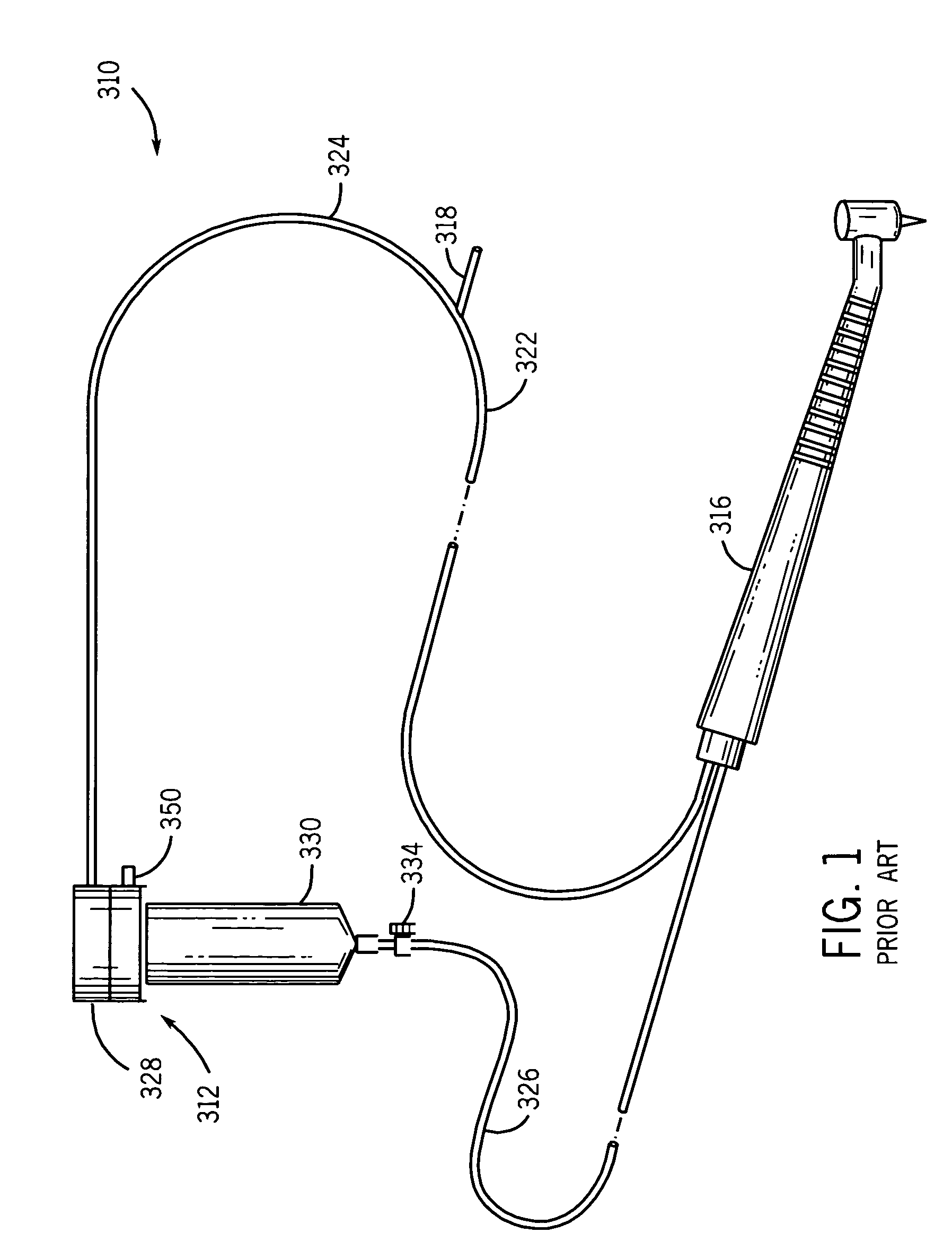
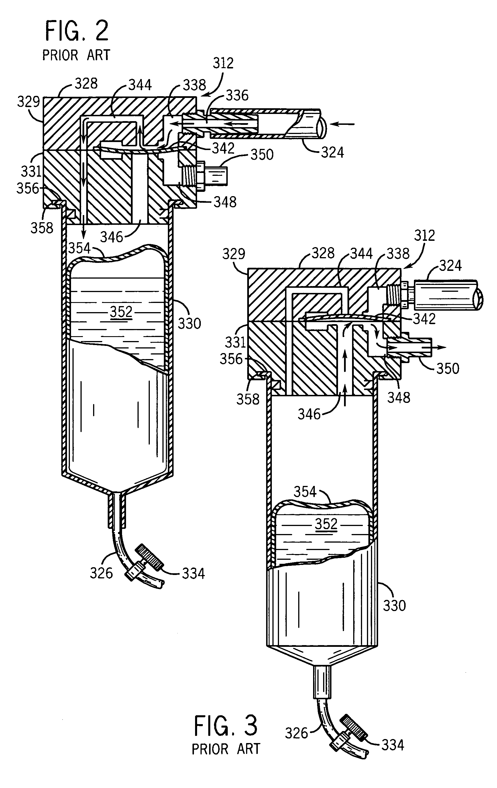
[0037]Referring to FIG. 1, a prior art dental handpiece drive system 310 is illustrated and includes a prior art coolant delivery system 312 disposed between a conventional pressurized-gas (air) source (not shown) and a conventional handpiece 316 and is operated by a conventional, selectively-operable, closable valve activated by a foot pedal (not shown) as known in the art. The pressurized-gas line 318 has two branches 322, 324, with the first branch 322 thereof leading directly to the handpiece 316 to thereby operate a conventional turbine drive in the handpiece as known in the art within the handpiece 316. The second branch 324 of the pressurized-gas line 318 leads to the coolant delivery system 312 for pressurization of coolant therein and ultimate delivery therefrom through a conduit 326 to the handpiece 316. The coolant delivery system 312 includes a pressurized-gas distribution structure 328 and a removable reservoir 330 where coolant, for example water, is housed. Desired co...


PUM


Abstract

A dental fluid delivery system for use with a dental drill is disclosed. The dental fluid delivery system includes a coolant water supply, a drive air line, a water line, and a coolant mist air controller. The coolant water supply unit includes a controller and a water container. The controller has a drive air inlet, a water inlet communicatively connected to the water container, a drive air outlet, and a water outlet. The drive air line is connected to the drive air outlet of the water supply unit. The water line is connected to the water outlet of the water supply unit. The coolant mist air controller is connectable in use to a dental drill. The mist air controller has a drive air inlet, a drive air outlet, a water inlet, a water outlet, and a mist air outlet.

Description

CROSS-REFERENCE TO RELATED APPLICATIONS, IF ANY[0001]Not applicable.STATEMENT REGARDING FEDERALLY SPONSORED RESEARCH OR DEVELOPMENT[0002]Not applicable.REFERENCE TO A MICROFICHE APPENDIX, IF ANY[0003]Not applicable.BACKGROUND[0004]1. Field[0005]The present invention relates, generally, to dental apparatus and methods. More particularly, the invention relates to dental drills, irrigators and air supplies. Most particularly, the invention relates to a system, apparatus and methods for providing drive, coolant, irrigation liquids, and mist air in a dental handpiece. The techniques of the invention can also be used in other fields such as medical and veterinary medical apparatus and methods.[0006]2. Background Information[0007]Dental hand pieces may provide means for drilling, drilling coolant, irrigation, mist air, air, and combinations thereof.[0008]High speed drills and the like used in preparing teeth for filings and other work require that such equipment be kept at a temperature su...

Claims


Application Information

Patent Timeline
Patent Type & Authority Patents(United States)
IPC IPC(8): A61C1/10
CPCA61C1/0084A61C1/0061
Inventor VARNES, DEWAYNE L.
Owner ANDERSON MARK L DR
Why Eureka
Try Eureka