Compact condensation particle counter technology

a technology of condensation particle and counter, which is applied in the field of analytical methods and apparatus for analyzing materials, can solve the problems of increasing the response time of these devices, cumbersome flow geometry, and significant limitations of the existing technology in this field, and achieves the effects of improving the background technology, being reliable, accurate and efficient, and being practical

Active Publication Date: 2021-11-23
KANOMAX FMT INC
View PDF4 Cites 0 Cited by
  • Summary
  • Abstract
  • Description
  • Claims
  • Application Information

AI Technical Summary

Benefits of technology

[0011]The present invention provides particle-vapor reactor (PVR) apparatus which is practical, reliable, accurate and efficient, and which are believed to constitute an improvement over the background technology.
[0019]D. The reactor of aspect C, wherein the dimensions of the obround section of the fluid flow conduit reduce residence time of fluid flowing within the fluid flow conduit for a given vapor concentration.
[0020]E. The reactor of claim C, wherein the transition from obround to circular at the outlet end minimizes loss of vapor droplets due to inertia.

Problems solved by technology

Existing technology in this field is believed to have significant limitations and shortcomings.
For example, systems used to modify particle properties by vapor exposure require long sample paths (for cylindrical conduits) or cumbersome flow geometry (for rectangular conduits).
The additional length and flow geometries increase the response time of these devices as well as increase particle deposition to the walls of the flow conduit.

Method used


Image

  • Compact condensation particle counter technology
  • Compact condensation particle counter technology
  • Compact condensation particle counter technology

Examples


first embodiment

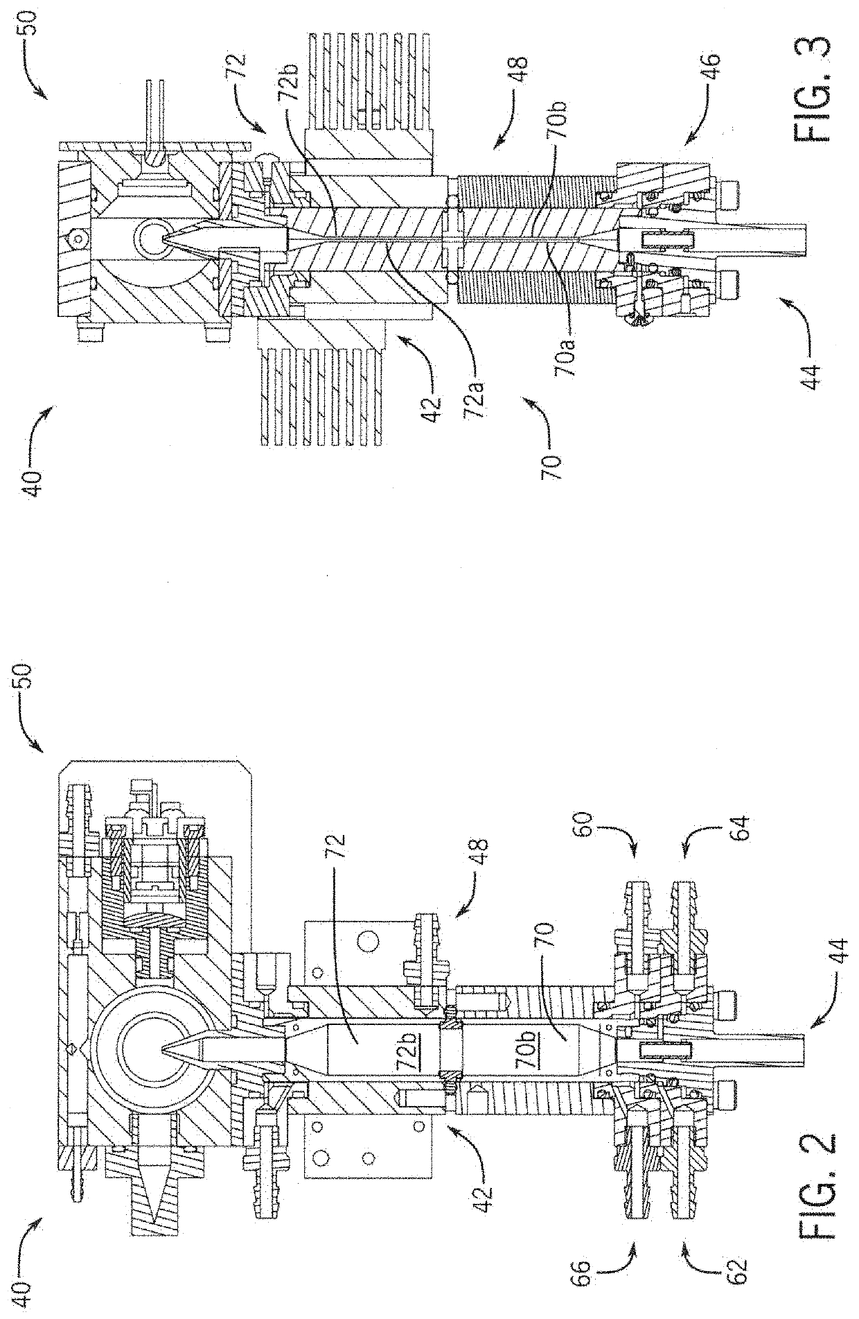
[0075]FIGS. 2 and 3 show the Condensation Particle Counter (CPC) 40 of the invention. The CPC 40 includes a Particle-Vapor Reactor (PVR) 42, an aerosol inlet 44, a fluid supply section 46, a heating section 48, and an optical detection section 50. In this embodiment, the CPC 40 includes sample sheathing functionality. The fluid supply section 46 includes a liquid supply 60, a sheath inlet 62, a transport outlet 64, and a vent 66. The PVR 42 amplifies the size of Nano-particles for optical detection in section 50.

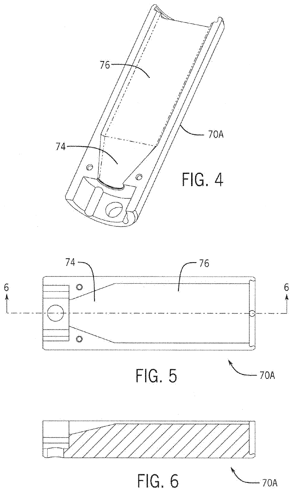
[0076]Referring also to FIGS. 4-6, in this embodiment of the invention, the PVR 42 has an elongated body of a predetermined length. The body wall defines an inner, longitudinally oriented fluid flow conduit or lumen which extends from an input end (shown disposed at the lower or bottom end in the drawings) and an outlet end (shown disposed at the upper or top end in the drawings). The PVR 42 conduit has a conditioner or saturator section 70 and a growth or condenser section ...

second embodiment

[0083]the CPC 100 is shown in FIGS. 8-10. The CPC 100 includes a PVR 102, an aerosol inlet 104, a fluid supply section 106, a heating section 108, and an optical detection section 110. In this embodiment, the CPC 100 includes sample sheathing functionality. The fluid supply section 106 preferably includes liquid supply, a sheath inlet, a transport outlet and a vent ingress / egress means. Such means may be associated with pumps. The PVR 102 functions include amplifying the size of Nano-particles for optical detection in section 110.

[0084]Referring also to FIGS. 12-15, in this embodiment of the invention, the PVR 102 also has an elongated body of a predetermined length. The body wall defines an inner, longitudinally oriented fluid flow conduit which extends from an input end (shown disposed at the lower or bottom end in the drawings) and an outlet end (shown disposed at the upper or top end in the drawings). The PVR 102 conduit has a saturator or saturation section 120 and a 110 conden...


PUM

PropertyMeasurementUnit
velocityaaaaaaaaaa
lengthaaaaaaaaaa
widthaaaaaaaaaa

Abstract

A particle vapor reactor (PVR) includes a reactor body with a fluid flow conduit having an inlet end and an outlet end, the crossection of the conduit having a circular geometry at the inlet end, a rectangular geometry at its midsection, and a circular geometry at its outlet end. The PVR conduit defines a saturator section and a condenser section. A compact condensation particle counter (CPC) including the reactor is also disclosed. The CPC also includes a sample inlet, a fluid inlet section, a heater section, and a detector section.

Description

CROSS-REFERENCE TO RELATED APPLICATIONS, IF ANY[0001]This application claims the benefit under 35 U.S.C. § 119(e) of U.S. Provisional Patent Application Ser. No. 62 / 311,997, filed Mar. 23, 2016, which is hereby incorporated by reference.37 C.F.R. § 1.71(e) AUTHORIZATION[0002]A portion of the disclosure of this patent document contains material which is subject to copyright protection. The copyright owner has no objection to the facsimile reproduction by anyone of the patent document or the patent disclosure, as it appears in the US Patent and Trademark Office patent file or records, but otherwise reserves all copyright rights whatsoever.STATEMENT REGARDING FEDERALLY SPONSORED RESEARCH OR DEVELOPMENT[0003]Not applicable.REFERENCE TO A MICROFICHE APPENDIX, IF ANY[0004]Not applicable.BACKGROUND OF THE INVENTION[0005]1. Field of the Invention[0006]The present invention relates, generally, to analysis methods and apparatus for analyzing material. Particularly, the invention relates to me...

Claims


Application Information

Patent Timeline
Patent Type & Authority Patents(United States)
IPC IPC(8): G01N15/06B01L3/00G01N15/00
CPCG01N15/065G01N2015/0038G01N2015/0046G01N2015/0693
Inventor OBERREIT, DEREK
Owner KANOMAX FMT INC
Why Eureka
Try Eureka